SOI/DT 2002-07 eb
48
599 35 36-69
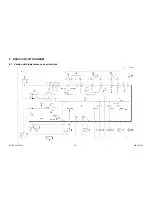
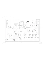
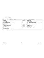
9.3 Key to circuit diagram
Components in the appliance
Components of the PCB
1. Electronic board
2. Suppressor
3. Door
interlock
4. 1st level pressure switch
5. Anti-boiling pressure switch
6.
Anti-overflow pressure switch
(some models)
7. Heating element
8. Stator
(motor)
9. Thermal overload cut-out (motor)
10. Tachometric generator (motor)
11. Rotor (motor)
12. Drain pump
13. Pre-wash solenoid valve
14. Wash solenoid valve
15. NTC temperature sensor
16. “Door locked” pilot lamp
(some models)
DOOR_TY
Interlock triac
DRAIN_TY
Drain pump triac
K1
Heating element relay
K2
Motor relay: clockwise rotation
K3
Motor relay: counter-clockwise rotation
K4
Motor relay: half-field power
(models with spin speed over 1200
rpm)
MOTOR_TY
Motor triac
ON/OFF
Main switch (on programme selector)
PWELW_TY
Pre-wash solenoid triac
Serial interface
Asynchronous serial interface
WELV_TY
Wash solenoid triac

