12
380 – 415V 3N
220 – 240V 3
220 – 240V 1N
C
S
C
S
C
S
6.9 kW
9.9 kW
12.9 kW
5x2.5 mm
2
5x2.5 mm
2
5x4 mm
2
16A 3P + N
20A 3P + N
32A 3P + N
4x4 mm
2
4x6 mm
2
4x10 mm
2
20A 3P
32A 3P
50A 3P
3x6 mm
2
3x10 mm
2
3x10 mm
2
40A 1P + N
60A 1P + N
70A 1P + N
C = Power supply cable
S = On/Off switch
NOTE!
Standard cycle time may vary should the inlet water temperature and/or the boiler heating elements be different from
that indicated above.
C.2
Characteristics of power supply
The AC power supply to the machine must meet the following conditions:
• max. voltage variation ± 6%
• max. frequency variation ± 1% continuous ± 2% for a short period.
Harmonic distorsion, unbalanced three-phase supply voltage, voltage pulses, interruption, dips and the other electric character-
istics must respect the provisions of point 4.3.2 of Standard EN 60204-1 (IEC 60204-1).
WARNING
The machine's power supply must be protected against overcurrents (short
circuits and overloads) by fuses or suitable thermal magnetic circuit breakers.
A suitable high-sensitivity manual-reset differential omnipolar thermal-
magnetic switch with contact gap enabling complete disconnection in
category III overvoltage conditions and complying with the current regula-
tions, must be installed between the power cable and the electric line.
WARNING
For protection against indirect contacts (depending on the type of supply
provided for and connection of earths to the equipotential protection circuit)
refer to point 6.3.3 of EN 60204-1 (IEC 60204-1) with the use of protection
devices that ensure automatic cut-off of the supply in case of isolation fault in
the TN or TT systems or, for IT systems, the use of isolation controllers or
differential current protection devices to activate automatic power disconnec-
tion (an isolation controller must be provided for indicating a possible first
earth fault of a live part, unless a protection device is supplied for switching off
the power in case of a such a fault. This device must activate an acoustic and/
or visual signal which must continue for the entire duration of the fault). For
example: in a TT system, a differential switch with cut-in current (e.g. 30 mA)
coordinated with the earthing system of the building where the machine is
located must be installed ahead of the supply.
D
TRANSPORT, HANDLING AND STORAGE
D.1
Introduction
Transport (i. e. transfer of the machine from one place to
another) and handling (i. e. transfer inside workplaces) must
occur with the use of special and adequate means.
WARNING
Due to their size, the machines
cannot be stacked on top of each
other during transport, handling
and storage; this eliminates any
risks of loads tipping over due to
stacking.
NOTE!
Specialised personnel must:
• have specific technical training and experience
in the use of lifting systems;
• have knowledge of the safety regulations and
applicable laws in the relevant sector;
• have knowledge of the general safety rules;
• ensure the use of personal protection equip-
ment suitable for the type of operation carried
out;
• be able to recognise and avoid any possible
hazard.
Содержание EHTA060
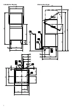
Страница 2: ...2 Installation diagram Manual hood type ...
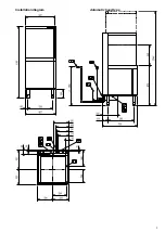
Страница 3: ...3 Installation diagram Automatic hood type ...
Страница 30: ......
Страница 31: ......
Страница 32: ...Electrolux Professional SPA Viale Treviso 15 33170 Pordenone www electroluxprofessional com ...

