


15
E.7
Disposal of packing
The packing must be disposed of in compliance with the
current regulations in the country where the appliance is used.
All the packing materials are environmentally friendly.
They can be safely kept, recycled or burned in an appropriate
waste incineration plant. Recyclable plastic parts are marked
as follows:
Polyethylene
• Outer wrapping
• Instructions bag
Polypropylene
• Straps
Polystyrene foam
• Corner protectors
The parts in wood and cardboard can be disposed of,
respecting the current regulations in the country where the
machine is used.
E.8
Plumbing connections
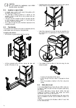
• Connect the appliance water supply pipe “WI“ (see the
) to the mains, fitting a cut-off tap, the
filter provided and a pressure gauge between the appliance
and the mains (see figure below).
• Check that the dynamic water supply pressure, measured
between the appliance and the main, is between between
50 and 700 kPa [0.5 - 7 bar] (test while dishwasher tank or
boiler is filling with water).
NOTE!
If the pressure is too high, fit a suitable pressure
reducer on the inlet pipe.
• On the model with free-fall drainage:
connect the waste outlet pipe (detail “D“ in the
) to the main drain pipe, fitting a trap, or place the
outlet pipe over an “S“ trap set into the floor.
• On the model with drain pump:
position the outlet pipe at a height anywhere between 750
and 1000 mm from the floor. Check that about 3 litres of
water flow out of the outlet pipe during the rinse cycle.
CAUTION
Always use a new set of joints if you
remove and reinstall the water inlet pipe to
the appliance.
IMPORTANT
Watermark labelled appliances must be installed in
accordance with AS/NZS 3500.1 and drainage to
be in accordance with 3500.2. On models with ESD,
an approved dual check valve must be installed
upstream.
E.9
Plumbing circuits
Hood dishwasher with drain pump
LEGEND
•
WI =
Water inlet
•
D =
Drain
•
M1 =
Wash pump
•
M3 =
Rinse pump
•
M4 =
Drain pump
•
AG =
Air Gap
•
YV1 =
Filling solenoid valve
E.10
Electrical connections
WARNING
Work on the electrical systems
must only be carried out by a
specialised personnel.
• Connection to the power supply must be carried out in
compliance with the regulations and provisions in force in
the country of use.
• Make sure the machine power supply voltage specified on
the rating plate matches the mains voltage.
• Make sure the system power supply is arranged and able to
take the actual current load and that it is executed in a
workmanlike manner according to the regulations in force in
the country of use.
• The earth wire from the terminal board side must be longer
(max 20 mm) than the phase wires.
• Connect the power cable earth wire to an efficient earth.
The equipment must also be included in an equipotential
system, whose connection is made by means of screw EQ
(see par.
) indicated by the symbol
.
The equipotential wire must have a section of at least 10
mm
2
.
!
Содержание EHTA060
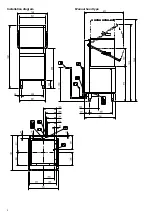
Страница 2: ...2 Installation diagram Manual hood type ...
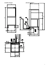
Страница 3: ...3 Installation diagram Automatic hood type ...
Страница 30: ......
Страница 31: ......
Страница 32: ...Electrolux Professional SPA Viale Treviso 15 33170 Pordenone www electroluxprofessional com ...


