


10
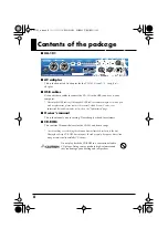
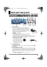
Front and rear panel
fig.front.eps_60
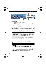
4.
Limiter switch
This turns the UA-101’s hardware limiter on/off.
Even if a high-volume audio signal is suddenly received at the
combo input
jacks (1)
, this limiter will apply mild compression to prevent clipping noise from
occurring before the AD converter.
* Clipping noise will occur if the input exceeds the capacity of the limiter.
5.
Input/output level indicators
These LEDs will light according to the level of the input signals at the
combo input
jacks (1)
and the monitor output signals (immediately before the monitor volume).
(Refer to the block diagram
➔
front cover)
When signals are being input from the
combo input jacks (1)
, these LEDs
function as input level indicators. If there is no input signal for a time, the LEDs will
switch to functioning as monitor output indicators.
6.
Sync indicator
When the
digital input switch (7)
is on, this indicates the state of
synchronization with the digital device connected to the
digital input connector
(8)
.
7.
Digital input switch
Turn this on ( pressed inward) if you’re recording from the digital input. This lets
you synchronize the UA-101 with an external digital device connected to the
digital input connector (8)
. (External synchronization mode)
When functioning as
input level indicators
The LEDs will light red at a level immediately
before distortion occurs (- 6 dB). Use the
input
sensitivity knobs (2)
to adjust the input lev-
el so that the red LEDs do not light.
When functioning as
monitor output level indicators
The LEDs will light red when the sound being output
to the monitor output jacks reaches a level immedi-
ately before distortion (0 dB). If the LEDs light red,
lower the monitor output volume in the
Lit
Synchronized correctly.
Blinking
Not synchronized correctly. Make sure that the digital device is correctly
connected to the digital input connector.
Also make sure that the sample rate of the connected digital device matches
the setting of the UA-101’s
sample rate select switch (10)
.
2
8
7
16
9
13
1
4
5
6
11 12
10
14
15
3
17
UA-101_e.book 10 ページ 2007年8月6日 月曜日 午後1時23分