1
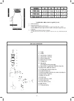
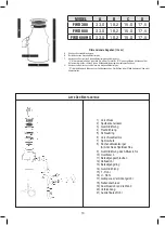
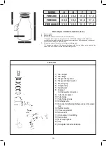
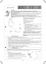
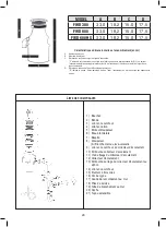
MODEL
A
B
C
D
TR 23
31,1 17,5 15,0 17,0
TR 510
31,1 17,5 15,0 17,0
TR 710
31,4 19,1 15,0 17,0
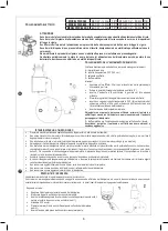
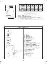
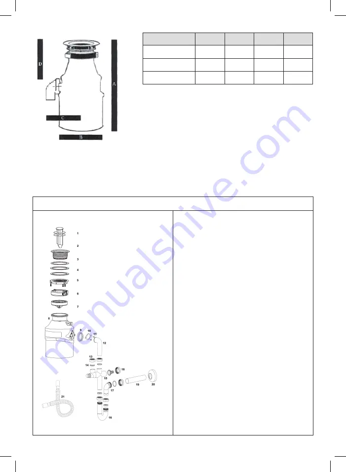
Waste disposer installation dimension (in cm.)
A.
Disposer Height;
B.
Disposer Width;
C.
Distance from disposer vertical centerline to the discharge tube;
“C” indicates the maximum ray required under the sink. With the following formula B+(C/3), it is
possible to approximately calculate the maximum space required on the drainage side: the disposer
should then be oriented in a convenient way.
D.
Distance from bottom of the sink bowl to the disposer discharge outlet;
“D” indicates the distance of the disposer discharge outlet from the bottom of the sink bowl: the
kitchen drain must be lower than the disposer discharge outlet.
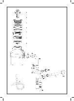
PARTS LIST
1) Sink stopper
2) Sink flange
3) Flange rubber gasket
4) Flange cardboard washer
5) Mounting ring
6) Hinged clamp
7) Splashguard
8) Disposer
(A) Dishwasher connection
9) Tube rubber gasket
10) Tube flange
11) Tube flange screws
12) Discharge tube
13) Ring cap for tightening discharge tube to the waste
trap
14) Rubber washer
15) Three way element
16) Goose neck
17) Union elbow for wall fitting
18) Service inlet
19) Wall coupling tube
20) Cap
21) Corrugated and extensible pipe
16
1
MODEL
A
B
C
D
TR 23
31,1 17,5 15,0 17,0
TR 510
31,1 17,5 15,0 17,0
TR 710
31,4 19,1 15,0 17,0
Waste disposer installation dimension (in cm.)
A.
Disposer Height;
B.
Disposer Width;
C.
Distance from disposer vertical centerline to the discharge tube;
“C” indicates the maximum ray required under the sink. With the following formula B+(C/3), it is
possible to approximately calculate the maximum space required on the drainage side: the disposer
should then be oriented in a convenient way.
D.
Distance from bottom of the sink bowl to the disposer discharge outlet;
“D” indicates the distance of the disposer discharge outlet from the bottom of the sink bowl: the
kitchen drain must be lower than the disposer discharge outlet.
PARTS LIST
1) Sink stopper
2) Sink flange
3) Flange rubber gasket
4) Flange cardboard washer
5) Mounting ring
6) Hinged clamp
7) Splashguard
8) Disposer
(A) Dishwasher connection
9) Tube rubber gasket
10) Tube flange
11) Tube flange screws
12) Discharge tube
13) Ring cap for tightening discharge tube to the waste
trap
14) Rubber washer
15) Three way element
16) Goose neck
17) Union elbow for wall fitting
18) Service inlet
19) Wall coupling tube
20) Cap
21) Corrugated and extensible pipe
1
MODELLO
A
B
C
D
TR 23
31,1 17,5 15,0 17,0
TR 510
31,1 17,5 15,0 17,0
TR 710
31,4 19,1 15,0 17,0
Caratteristiche dimensionali e ingombri (in cm.)
A.
Altezza del dissipatore;
B.
Diametro del dissipatore;
C.
Distanza dal centro del dissipatore al tubo di scarico;
“C” indica il raggio massimo in tale zona mentre con la seguente formula B+(C/3) , si ottiene
approssimativamente il massimo ingombro sul lato di scarico: orientare quindi il dissipatore in modo
conveniente.
D.
Distanza dalla base del lavello allo scarico del dissipatore;
“D” indica la quota di scarico dal fondo del lavello: lo scarico a muro non dovrebbe superare tale
quota.
L
ISTA DEI COMPONENTI
1) Tappo
2) Piletta
3) Guarnizione in gomma
4) Guarnizione in cartone
5) Ghiera dissipatore
6) Morsetto con cerniera
7) Paraspruzzi
8) Dissipatore
(A) Collegamento lavastoviglie
9) Guarnizione in gomma del collettore di scarico
10) Ghiera del collettore di scarico
11) Viti fissaggio collettore di scarico
12) Collettore di scarico
13) Ghiera serraggio collettore di scarico alla sifoneria
14) Guarnizione in gomma
15) Elemento a tre vie
16) Collo d’oca
17) Curva raccordo a muro
18) Presa di servizio
19) Tubo innesto a muro
20) Mascherina
21) Tubo estensibile
MODEL
A
B
C
D
FWD 380
33,0
18,2
15,0
17,5
FWD 600
33,0
18,2
15,0
17,5
FWD 600 HS
33,0
18,2
15,0
17,5
Содержание FWD 380
Страница 2: ......
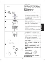
Страница 47: ...6 e 2 5 4 la parte 2 3 5 4 7 8 7 8 2 6 12 10 12 9 12 12 8 12 15 A 16 15 17 19 15 8A 8A 21 8A 2 47...
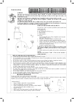
Страница 49: ...4 1 e 2 3 4 5 1 2 5 10 3 4 5 1 9 9 o o A o o reset o o A o o o o o o o o o o o o o o o o 5 Reset o o reset 2 49...
Страница 51: ......
Страница 52: ......

