a measurable difference!
®
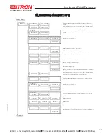
FROM PART 1
Analog cards only
if AO1 SGNL=mA
if AO1 SGNL=VDC
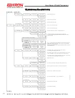
AO2 output is assigned as temperature output.
if AO2 SGNL=mA
if AO2 SGNL=VDC
if AO2 CFG=TEMP
if AO2 CFG=ALRM or TRBL
TO PART 3
NO FAULT = HI
Set AO1 output units to FPM or CFM. (Note: A-ACT or
S-STD measurement is set by AIRFLOW= setting above).
*AO2 MS=-20
SET AO2 MS?
AO2 MS=-20
*AO2 FS=160
AO2 RNGE=0-5
*AO2 UM=F
AO2 UNITS FIXED
The text "AO2 UNITS FIXED" flashes to indicate that this setting is fixed and cannot be
modified.
*NO FAULT = HI
SET NO FAULT?
NO FAULT = LO
AO2 RNGE=FIXED
The text "AO2 RNGE=FIXED" flashes to indicate that this setting is fixed and cannot be
modified.
*AO2 RNGE=0-10
SET AO2 RNGE?
AO2 RNGE=0-10
Set analog output range (VDC) for AO2.
SET AO2 FS?
Integration samples. Also same as network integration.
*AO2 ASGN=TEMP
SET AO2 ASGN?
AO2 ASGN=TEMP
AO2 ASGN=ALRM
*A02 SGNL=mA
SET SW2 ON PCB
Display initially shows the current SW2 PCB switch setting (VDC or mA) for AO2. Pressing
enter displays "SET SW2 ON PCB" prompt to confirm SW2 PCB setting.
AO2 output is assigned as an airflow alarm output.
Refer to ALARM settings (part 4).
AO2 FS=160
*AO1 FS=5000
SET AO1 FS?
AO1 FS=5000
AO2 ASGN=TRBL
*AO1 INTG=30
SET AO1 INTG?
AO1 INTG=30
SET AO1 RNGE?
Set analog output range (VDC) for AO1.
AO1 RNGE=0-10
AO1 RNGE=0-5
*AO1 UM=AFPM
SET AO1 UM?
*A01 SGNL=mA
SET SW1 ON PCB
Display initially shows the current SW1 PCB switch setting (VDC or mA) for AO1. Pressing
enter displays "SET SW1 ON PCB" prompt to confirm SW1 PCB setting.
*AO1 RNGE=4-20
AO1 RNGE=FIXED
The text "AO1 RNGE=FIXED" flashes to indicate that this setting is fixed and cannot be
modified.
The text "AO1 ASGN FIXED" flashes to indicate that this setting is fixed and cannot be
modified.
ANALOG OUT
*AO1 ASGN=FLOW
AO1 UM=AFPM
AO1 ASGN FIXED
AO2 output is assigned as a transmitter trouble alarm indicating that a sensor or transmitter
fault has occurred.
Sets AO2 alarm/trouble output state when no fault condition is present, expressed as HI (full
scale analog output) or LO (minimum scale analog output).
AO1 UM=ACFM
Set full scale for AO1. FS default value is dependent on probe type connected.
O
*AO1 RNGE=0-10
*AO2 RNGE=4-20
O
Set AO2 minimum scale.
Set AO2 full scale.
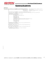
TM_GTx116 Setup Menu (PART 2 OF 6)
39
EBTRON
, Inc. 1663 Hwy. 701 S., Loris SC 29569
•
Toll Free: 800.2
EBTRON
(232.8766)
•
Fax: 843.756.1838
•
Internet:
EBTRON
.com
G
OLD
S
ERIES
GT
X
116 T
RANSMITTER
a measurable difference!
®
TM_G
Tx1
1
6_R9A


