a measurable difference!
®
Procedure for 1 Point Field Adjustment
Select an airflow rate that represents a valid operating condition for the system. Set fan speed, dampers and VAV boxes
to a fixed speed or position when measurements are taken. Complete the following worksheet to determine the gain set-
ting to be set on the transmitter.
1.
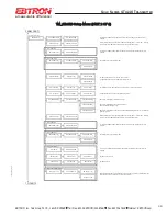
Enter the setup menu and set “*FLOW ADJ=OFF”. This is the factory default setting and disables any adjust-
ments, returning the unit to its original factory calibration.
2. __________ Record the transmitter output by taking the visual reading from the transmitter LCD. Readings can
be taken by the host controls if the output signal conversion has been confirmed. Time averaging the data will
improve field recalibration.
3. __________ Record the reference reading. Make sure that the unit of measure (FPM, CFM) is identical for both
the transmitter and the reference. If the unit of measure is velocity (FPM), make sure that the reference airflow
measurement was corrected for the area where the measurement was taken.
4. __________ Calculate the gain factor (m): m=line 3/line 2.
5.
Enter the setup menu and set “*FLOW ADJ=ON”.
6.
Set “*GAIN={value calculated in line 4}”.
7.
Confirm that “*OFF=0.00”.
8.
Press the “ESC” button until you return to the normal operating mode. Field adjustment is complete.
Procedure for 2 Point Field Adjustment
Select the minimum and maximum airflow rate that the airflow station will encounter as a valid operating condi-
tion for the system. Set fan speed, dampers and VAV boxes to a fixed speed or position when measurements are
taken. Complete the following worksheet to determine the gain and offset settings to be set on the transmitter.
Measurement units can be in either FPM or CFM, but they need to be the same between transmitter and refer-
ence.When using FPM, ensure that area for both measurements is the same.
1.
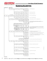
Enter the setup menu and set “*FLOW ADJ=OFF”. This is the factory default setting and disables any adjust-
ments, returning the unit to its original factory calibration. OBSERVE AND APPLY MEASUREMENT UNITS FOR CON-
SISTENCY BETWEEN TRANSMITTER AND REFERENCE.
2.
Set the minimum airflow rate.
3. __________ Record the transmitter airflow rate by taking the visual reading from the transmitter LCD. Readings
can be taken by the host controls if the output signal conversion has been confirmed. Time averaging the data will
improve field recalibration.
4. __________ Record the reference airflow rate. Make sure that the reference airflow measurement was correct-
ed for the area where the measurement was taken.
5.
Set the maximum airflow rate.
6. __________ Record the transmitter airflow rate.
7. __________ Record the reference airflow rate.
8. __________ Calculate the gain factor (m): m=(line 7 - line 4)/(line 6 - line 3).
9. __________ Calculate the offset factor (b): b=(line 4 - (line 8 x line 3).
If more than 2 points are available, perform a linear regression on the data to determine gain and offset.
10. Enter the setup menu and set “*FLOW ADJ=ON”.
11. Set “*GAIN={value calculated in line 8}”.
12. Set “*OFF={value calculated in line 9}”. Note that OFFSET must be entered in FPM. If measurements were
recorded in CFM then values need to be divided by duct area before entering in transmitter.
13. Press the “ESC” button until you return to the normal operating mode. Field adjustment is complete.
30
EBTRON
, Inc. 1663 Hwy. 701 S., Loris SC 29569
•
Toll Free: 800.2
EBTRON
(232.8766)
•
Fax: 843.756.1838
•
Internet:
EBTRON
.com
G
OLD
S
ERIES
GT
X
116 T
RANSMITTER
a measurable difference!
®
TM_G
Tx1
1
6_R9A

