Display
Description
I-P
S.I.
AIRFLOW=
Airflow measurement method, Actual or Standard.
ACT
ACT
*LCDU/M=
Airflow units of measure
ACFM
LPS
*AREA=
Free area where station is located (required for volumetric measurement)
0.00 sq.ft.
(see note)
0.000 sq.meters
(see note)
*AO1 SGNL=
GTC/GTM116 output 1 signal type voltage or mA (airflow)
mA
mA
*AO1 UM=
Output 1 units of measure
AFPM
MPS
*AO1 FS=
GTC/GTM116 output 1 signal full scale
5,000 FPM
25 MPS
*LLIMIT=
GTC/GTM116 low limit cutoff
0 AFPM
0 AMPS
*FLOW ADJ=
Output 1 Offset-Gain On/Off
Off
Off
*GAIN=
Output 1 Gain factor
1.000
1.000
*OFF=
Output 1 Offset factor
0.000
0.000
*TEMP METH=
Temperature Averaging
Weighted Avg.
Weighted Avg.
*AO2 SGNL=
GTC/GTM116 output 2 signal voltage or mA (temperature or alarm)
mA (see alarms)
mA (see alarms)
*AO2 MS=
GTC/GTM116 output 2 signal minimum scale
-20º F
-30º C
*AO2 FS=
GTC/GTM116 output 2 signal full scale
160º F
70º C
*LCD INTG=
Number of flow calculations to be averaged for LCD display.
100
100
*AO1 INTG=
Number of flow calculations to be averaged for AO1 output.
30
30
*EB-LK INT=
Number of flow calculations to be averaged for EB-Link readings.
300
300
*ALT=
Altitude for flow correction relative to mean sea level (0 ft).
0 ft
0 m
*AO2 ASGN =
Output 2 Assigned Type: Temperature/Alarm
TEMP
TEMP
*SETPNT=
Alarm setpoint value. When AO2 ASGN=ALARM , operates in conjuction with
TOL= value.
0
0
*TOL=
Alarm range tolerance value. When AO2 ASGN=ALARM , this setting establishes
the alarm range relative to the S
SETPNT= value.
10%
10%
*NO FAULT=
Sets the AO2 normal (not alarm) output state relative to the full scale analog
output selected. H
HI provides maximum full scale under normal conditions and
minimum scale during alarm. L
LO provides minimum full scale under normal
conditions and maximum scale during alarm.
HI
HI
*DELAY=
Time that the alarm condition must exist before alarm output is activated.
2 minutes
2 minutes
*ZERO OFF =
Set to Y
YES to inhibit LO alarm condition when flow reading is zero (dependent on
LLIMIT= setting). Set to N
NO to disable this feature.
NO
NO
*RESET =
Set to A
AUTO to have alarm self-clear when alarm condition no longer exists. Set
to M
MANUAL to require manual reset of alarm.
AUTO
AUTO
Note: For GP1 probes, area is stored in one-wire, but can be changed.
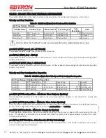
Table 4. Factory Default Menu Settings
Factory Default Menu Settings for GP1 Sensor Probes
The GTx116 transmitter is “plug and play” and does not require setup unless a network option is selected that requires
configuration. Table 4 shows the factory default settings for all compatible sensor probes.
To change the Factory Default Settings, see: CHANGING FACTORY DEFAULT SETUP MENU SETTINGS.
13
EBTRON
, Inc. 1663 Hwy. 701 S., Loris SC 29569
•
Toll Free: 800.2
EBTRON
(232.8766)
•
Fax: 843.756.1838
•
Internet:
EBTRON
.com
G
OLD
S
ERIES
GT
X
116 T
RANSMITTER
a measurable difference!
®
TM_G
Tx1
1
6_R9A


