


PC
EA
W
PILOT
UX
88
00 "A"
U-
N
et
1
U-
N
et
2
Ethernet
U-
N
et
1
U-
N
et
2
JF
N
T
/KF
N
T
U-
N
et
1
U-
N
et
2
TO
N
EXT JF
N
T
/KF
N
T
FROM LAST JF
N
T
/KF
N
T
JF
N
T
/KF
N
T
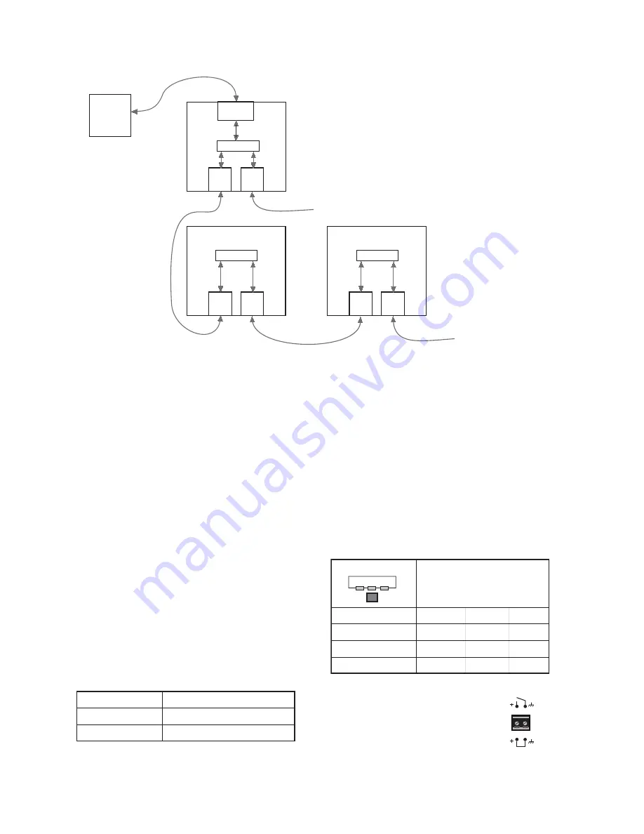
Connect one of the U-Net ports on the
UX8800’s rear panel to a U-Net port on
the JF
NT
/KF
NT
. If there are more than one
JF
NT
/KF
NT
, connect the other U-Net port
on the JF
NT
/KF
NT
to the next JF
NT
/KF
NT
,
and so on. This configuration is used to rout
any number of UX8800 outputs to the
JF
NT
/KF
NT
s on the U-Net chain. Again,
EAWPilot is used for U-Net configuration.
It is recommended that you connect the first free U-Net port to the first JF
NT
/KF
NT
. A ring is created
so the audio and control signals have two paths along the network, and the integrity of the network is
maintained in the event that one JF
NT
/KF
NT
should go offline.
There is no requirement to connect Port 1 to Port 2 or vice versa. Signals are sent out both U-Net
ports bi-directionally so any port can be connected to any other port. It is recommended, however,
that the JF
NT
/KF
NT
s be connected sequentially, top down or bottom up in an array.
7 . 6
O p e r a t i n g C o n t r o l s
The operating controls on the JF
NT
/KF
NT
rear panel are momentary contact, “soft” switches. This
means that they control software that does the actual switching with status lights indicating the switch
“position.” Pressing a switch repeatedly will cycle through its available options.
7.6.1
INPUT SELECT
Repeatedly press the switch between the XLR input
connectors to cycle through and select the desired input signal
type.
Press and hold the switch for five seconds to bypass the user-
adjustable DSP (accessible from EAWPilot). Repeat to enable
the user DSP.
LED flashing = DSP enabled
LED constant = DSP disabled
NOTE:
U-Net can be selected with the
Input Select switch, but the U-Net audio
channel and routing must be configured
using the EAWPilot software
application.
OPE
N
CLOSED
FULLY FU
N
CTIO
N
AL
STA
N
DBY
CONTACTS
ELECTRONICS STATUS
ENABLE
STANDBY
ALL ON = U-NET INPUT
INPUT SELECT
AES/EBU
CH 2
AES/EBU
CH 1
NORM/
ANALOG
NORM/ANALOG
AES/EBU CH1
AES/EBU CH2
U-NET
OFF
O
N
OFF
O
N
O
N
OFF
OFF
O
N
OFF
OFF
O
N
O
N
LED STATUS
21


