


14
Initial Set-Up
Introduction to
Programming
To operate the SMC20 you must have a
program (a series of commands that
define, monitor, and govern the
controller’s activities).
Use of the Hand-Held Terminal makes it
unnecessary to learn a special
language. It is still necessary to
understand the order in which various
features should be used and to properly
interpret the abbreviated instructions
made necessary by the small input
device display.
The Hand-Held Terminal is attached to
the RS422/485 port on the lower right
corner of the SMC20 front panel.
Hand–Held Terminal
The Terminal has five distinct modes of
operation, three of them for
programming, plus the Run and Monitor
modes.
Monitor
(MON)
Configuration
(CFG)
Variables
(VAR)
Program Segment
(PRG)
Under Program, there is a major
sub-mode, Segment, which does
not have a panel button.
Run
(RUN)
When power is turned on, the screen
displays the hardware version numbers
and a message: “Hit <Clear Entry> Key”
as shown below:
SMC20 VER X X
F1
F2
F3
HIT <CLR ENTRY> KEY
F4
If no security code has been set up,
pressing any key will automatically set
the screen display to the Monitor (MON)
mode. As shipped, the security code is
set to a default value of 0, which implies
no protection.
MONITOR MOTION
↑
AXIS
F1
POS 1 0 0000 <SEL
F2
PER 1 0 0000 <SEL
F3
VEL 1 0 0000
↓
<SEL
F4
Each of the modes, MON, CFG, VAR,
PRG, RUN is discussed in detail in the
Programming section (page ##).
You can change to different modes by
pressing the corresponding key. MON,
CFG, VAR, PRG, RUN.
When words appear at the right edge of
the screen aligned with F1, F2, F3, or
F4, the word indicates the function of
that blue button for that screen. The
functions vary with the screen. When
Up/Down arrows appear, pushing the
green arrow keys will change the screen
or one of the choices on the screen.
Continued pushing of either Up or Down
keys will go through the entire list of
screens or choices available in that
mode or sub-mode. The choices always
form a circular list.
When screens say EDIT, pushing that
key leads to a lower level with several
screens. When the screen shows
<EDT, a single value is to be edited.
On some screens the word EDIT is
spelled out. Selecting this function takes
the user into other screens for editing.
The <EDT form means the value pointed
to (and in brackets) can be edited. No
screen changes will occur.
On screens for value or name entry,
CLEAR ENTRY, ENTER, and
BACKSPACE are active. F1 and F2 can
be used to move the cursor if the entry is
to be edited rather than being cleared
and completely re-entered. To delete a
character or a digit, position the cursor
(blinking square) to the right of the
character to be deleted and use the
backspace key. Otherwise, a character
entered at the cursor is inserted ahead
of the position where the cursor is, and
the cursor is pushed to the right.
When values are entered, in addition to
pushing ENTER on the value input
screen, it is necessary to push SAVE on
a preceding screen (after ENTER).
A program is not saved against power
turn–off until it is SAVED to FLASH
MEMORY from the CFG mode. It is
therefore, a good idea to save to FLASH
Memory frequently.
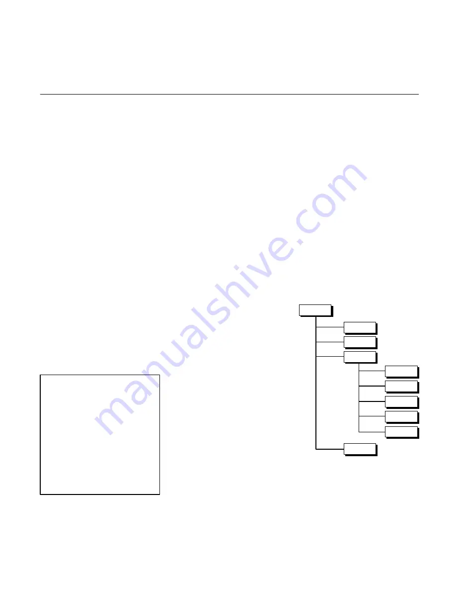
The SMC20 Programming
Structure
Each axis is independently programmed
at all levels. See Figure 3-1.
Figure 3-1. The SMC20 Programming
Hieracrcy
PROFILE
PROFILES
SEGMENT
AXIS
PROFILE
PROFILE
PROFILE
Axis
One actuator and associated equipment
and SMC20 connections.


