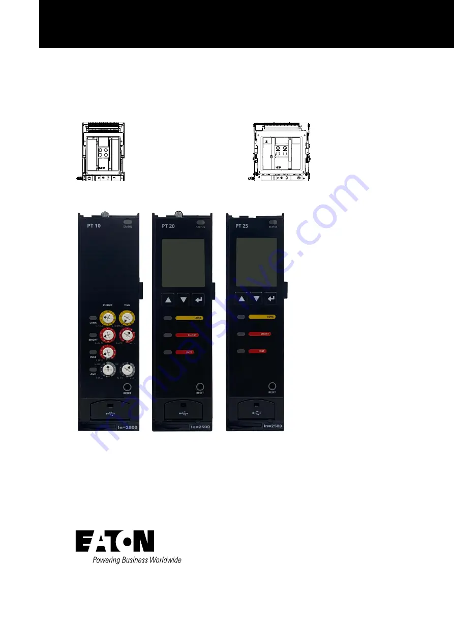
background image

PT 10/20/25 Trip Unit User Manual

Power Trip (PT) Units

Instruction Manual

  MN013018SC 

Instructions apply to::

CCC, new generation 

IZM61 series air 

circuit breaker

CCC, new generation 

IZM65 series air 

circuit breaker

CCC, new generation 

IZM67 series air 

circuit breaker

Содержание PT 10

Страница 1: ...al Power Trip PT Units Instruction Manual MN013018SC Instructions apply to CCC new generation IZM61 series air circuit breaker CCC new generation IZM65 series air circuit breaker CCC new generation IZ...

Страница 2: ...Functionality 9 3 4 Pickup Cause of Trip Indicator 9 3 5 Rotary Switches PT10 only 10 3 6 Reset Button 10 3 7 Door 10 3 8 USB 10 3 9 Battery 10 3 10 In Ratings 10 3 11 Side Labels 10 4 PT PROTECTION S...

Страница 3: ...NDARYWIRINGTERMINALSASSOCIATEDWITHTHEPTTRIPUNIT 22 9 TESTING THE TRIP UNIT AND CIRCUIT BREAKER 22 9 1 Functional Opening Test Local via Display 22 9 2 Simulated Current Test Remote via USB PTM Configu...

Страница 4: ...ct the circuit breaker before performing maintenance or tests Any tripping operation will cause disruption of service and possible personal injury resulting in the unnecessary switching of connected e...

Страница 5: ...ed by the current rating and user selected protection settings There is no mechanical or direct magnetic action between the primary current side and the mechanical tripping parts of the circuit breake...

Страница 6: ...etermine the current through the circuit breaker The mechanical action required to initiate tripping of the circuit breaker is provided by a special low energy trip actuator This trip actuator is an i...

Страница 7: ...nit Type Catalog Number Protection style LCD Rotary switch Ground fault Modbus RTU Zone inter lock Relay output Digital input PT 10 PT10 LSI PT10G LSIG PT 20 PT20 LSI PT20G LSIG PT20C LSI PT20GC LSIG...

Страница 8: ...ds 0 05 0 1 0 2 0 3 0 4 0 5 0 05 0 5 Adjustable step is 0 01 Zone Interlock Enable Disable Instantaneous Protection Instantenous x In Off 2 4 5 6 7 8 10 12 15 Off 2 15 Adjustable step is 0 1 Neutral P...

Страница 9: ...1 65500 adjustable Interval of 1 Reverse Power Delay s 1 300 adjustable Interval of 1 Frequency Protection Over frequency Pickup Hz 40 70 adjustable Interval of 1 When Phase A phase voltage exceeds 1...

Страница 10: ...it Accuracy Notes VAB VBC VCA Volts 0 5 of Reading Line to Line Voltage Minimum VAB VBC VCA Volts 0 5 of Reading Group values held until reset Maximum VAB VBC VCA Volts 0 5 of Reading Group values hel...

Страница 11: ...y Total kWh 2 5 of Reading Forward reverse Real Energy Net kWh 2 5 of Reading Forward reverse Real Energy Forward kWh 2 5 of Reading Delivered by source to load Real Energy Reverse kWh 2 5 of Reading...

Страница 12: ...rm Over temperature alarm Clock error See Appendix B Troubleshooting for details When the status indicator remains off there is no auxiliary power applied or insufficient primary current to power the...

Страница 13: ...ions from the main menu Each submenu can be accessed by highlighting the appropriate submenu by pressing the Down or Up Arrow buttons then the Enter button 3 3 Password Protection Functionality The cy...

Страница 14: ...monitor the trip unit A USB connection will also typically provide power from the host side of the USB cable to power up the trip unit when another source of auxiliary power is not available This con...

Страница 15: ...t Extremely inverse time current curve a steep protective slope for coordination with fuses or for special type of loads 4 1 2 Long Delay Thermal Memory In addition to the standard Long Delay protecti...

Страница 16: ...ections are indicated with an asterisk while the fixed time flat response time selections are indicated without an asterisk Both have a range from 0 1 seconds to 0 5 seconds PT20 25 For PT20 25 units...

Страница 17: ...flowing through the ground conductor When the current measured by the trip exceeds the ground fault setting the circuit breaker will trip or alarm The ground circuit sensing method is usually applied...

Страница 18: ...lay setting is reached the trip unit will act Power demand protection When the detected active power is greater than the defined power demand setting and the corresponding time delay setting is reache...

Страница 19: ...Zout of that breaker should wired to the Zin of the same breaker to provide a self interlocking feature Refer to Eaton Application Note AP02602002SC for detailed description and examples 4 6 8 Phase L...

Страница 20: ...breaker The index starts from zero and increases to 10 000 points depending on the conditions under which the circuit breaker operates The index remains in the frame module of the circuit breaker Chan...

Страница 21: ...ed by communications With CAM supported module closing release and shunt release Event Closed by communications Event Time change if 60 seconds Previous time is recorded Alarm Calibration Alarm Setpoi...

Страница 22: ...C VCA VAN VBN VCN PT25 only Power Watts Vars VA PT25 only Demand Watts Vars VA PT25 only Temperature Frequency PT25 only Power factor PT25 only Operations count User Waveform or Alarm Waveform Wavefor...

Страница 23: ...t point High Load 2 current flow is greater than set point adjustable from 50 to 120 of Ir current flow falls 5 below the set point Over Temperature Alarm temperature exceeds 5 below the level of the...

Страница 24: ...ESET button is pressed or communications reset command received Under frequency Alarm under frequency alarm is active and under frequency alarm has occurred RESET button is pressed or communications r...

Страница 25: ...d to supply power to the trip unit change and save relevant settings 7 Important System Components 7 1 Auxiliary Power Providing auxiliary power to the PT unit will provide full functionality even whe...

Страница 26: ...on and protection schemes the protection settings if altered during any test sequence should be reset to their as found values WARNING Do not attempt to install test or perform maintenance on equipmen...

Страница 27: ...y a test current of 125 of the ground pickup setting through one phase of the circuit breaker This should cause the circuit breaker to trip in less than one second and operate the alarm indicator if s...

Страница 28: ...for removal Figure 16 Location of the Top and Bottom Trip Unit Screws To install a new trip unit First connect the wiring harness at the top of the trip unit s control module such harness is not avail...

Страница 29: ...No Location Circuit Breaker Order Reference Amperes Rating In Continuous Ampere Rating Ir Protection Settings Circle the Selected Value Long Delay Pickup 0 4 0 5 0 6 0 7 75 0 8 0 9 95 98 1 0 Ir A Tim...

Страница 30: ...tes in a single Modbus transaction The trip unit responds to a limited number of Modbus function codes These are function codes 02 03 04 06 08 and 16 Function codes 03 and 04 are used interchangeably...

Страница 31: ...404623 406159 120E 180E VAB V 10 404625 406161 1210 1810 VBC V 10 404627 406163 1212 1812 VCA V 10 404631 406167 1216 1816 VAN V 10 404633 406169 1218 1818 VBN V 10 404635 406171 121A 181A VCN V 10 4...

Страница 32: ...m VCA V 10 404883 406419 1312 1912 Minimum VAN V 10 404885 406421 1314 1914 Maximum VAN V 10 404887 406423 1316 1916 Minimum VBN V 10 404889 406425 1318 1918 Maximum VBN V 10 404891 406427 131A 191A M...

Страница 33: ...der register and Register 0 is the low order register Register 3 high byte contains value corresponding to engineering units power of 10 signed exponent Register 3 low byte contains a mantissa multipl...

Страница 34: ...67 403004 4 0 0x000F Style R Encoded PT10 16 PT10G 17 PT20 18 PT20G 19 PT20C 20 PT20GC 21 PT25 22 PT25G 23 403005 Style 2 R Invalid 403006 0 0 Invalid R Invalid 403007 0 0 Invalid R Invalid 403008 Fre...

Страница 35: ...8 Remote control 29 Mechanical fault trip 30 Mechanical fault alarm 31 Electrical fault alarm 32 Over voltage trip 33 Over voltage alarm 34 Under voltage trip 35 Under voltage alarm 36 Over frequency...

Страница 36: ...ixed 1 Sliding 403020 7 0 0x00FF Demand Interval R W Unit Minute 5 to 60 minutes 403021 7 0 0x00FF Breaker Health Alarm Threshold R W Unit Percentage 50 to 100 403022 11 0 0x0FFF System Voltage R W Un...

Страница 37: ...pe R W Encoded 0 I0 5t 1 It 2 I2t 3 I4t 403009 6 0 0x007F Long Delay Pickup Ir R W Unsigned 40 100 step is 1 indicating 0 40 In 1 00 In 403010 7 0 0x00FF Long Delay Time tr R W Unsigned 5 240 step is...

Страница 38: ...ndicating 0 10 0 50 second 403021 0 0x0001 Ground Fault Thermal memory R W Encoded 0 Disabled 1 Enabled 403022 6 0 0x007F Neutral Protection Ratio R W Unsigned 0 0 60 60 100 100 403023 6 0 0x007F High...

Страница 39: ...00FF Voltage Unbalance Protection Threshold Setting R W Unsigned 5 25 step is 1 Unit 403010 11 0 0x0FFF Voltage Unbalance Protection Time Setting R W Unsigned 1 300 step is 1 Unit Seconds 403011 2 0 0...

Страница 40: ...Current Demand Protection Setting R W Encoded 0 Trip 1 Alarm 2 OFF 403030 11 0 0x0FFF Current Demand Protection Threshold Setting Phase A R W Unsigned 20 100 step is 1 indicating 0 2In 1 00In 403031 1...

Страница 41: ...s in the trip unit registers 408200 and 408202 provide the Previous Event ID and Next Event ID respectively If the requested event does not exist in the trip unit exception code 0x87 is returned The d...

Страница 42: ...Event ID 408198 Unsigned32 R W Requested Event ID 408200 Unsigned32 R Previous Event ID 408202 Unsigned32 R Next Event ID 408204 Date Time R Date Time 408212 Encoded R Format of Data Minor Alarm 00061...

Страница 43: ...register to provide compatibility and at a new register assignment below 9999 The format is given as low high register numbers followed by low16 high16 Modbus register addresses An example is 4xxxx 4y...

Страница 44: ...lock Definition Modbus Register Number Modbus Register Address Data Range Month 402921 0x0B68 1 12 Day 402922 0x0B69 1 31 Year 402923 0x0B6A Day of week 402924 0x0B6B 1 Sunday 7 Saturday Hour 402925 0...

Страница 45: ...er current 0x0054 Ground fault 0x0055 Earth fault 0x0071 Calibration 0x0088 Real time clock 0x009A Breaker mechanism fault 0x009E Short delay neutral over current 0x009F Thermal memory alarm 0x00A0 Lo...

Страница 46: ...The trip unit is malfunctioning Replace the trip unit The breaker trips too rapidly and reports long delay fault Long Time Thermal Memory Function is selected Disable the Long Time Thermal Memory for...

Страница 47: ...not indicating proper state Check the auxiliary switch See the Instructions for Auxiliary Switch The circuit breaker mechanism is not properly closed Contact your Eaton representative for factory assi...

Страница 48: ...the purchaser THERE ARE NO UNDERSTANDINGS AGREEMENTS WARRANTIES EXPRESSED OR IMPLIED INCLUDING WARRANTIES OF FITNESS FOR A PARTICULAR PURPOSE OR MERCHANTABILITY OTHER THAN THOSE SPECIFICALLY SET OUT I...

Отзывы: