8
PT UNIT USER MANUAL
APRIL 2023 www.eaton.com.cn
3. Power Trip (PT) Units
The PT unit is located on the front and to the left side
of the circuit breaker. It is encased in a housing which
provides protection to the electronics as well as providing
an interface for a user to configure protection settings and
monitor operation. Details of the interface and operation are
contained in the sections which follow. Certain features are
available only in selected PT unit styles.
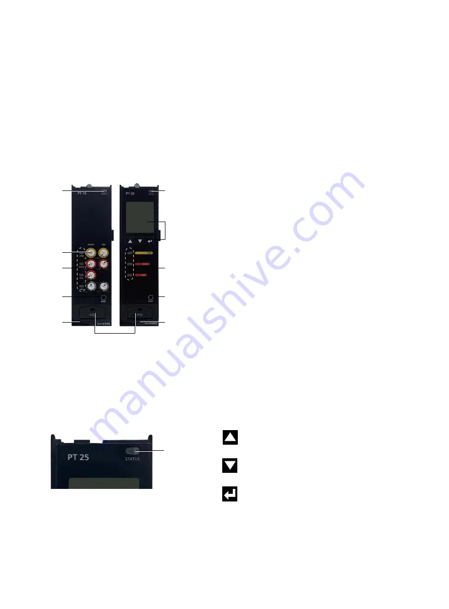
Figure 5. PT20/25 Unit Front Face
3.1 Status Indicator
All PT units have an indicator at the top right labeled
“STATUS”. During normal operation, this indicator blinks green
(on and off approximately once each second), indicating that
the trip unit is operating normally.
Figure 6. Status Indicator
3. Power Trip (PT) Units
The status indicator blinks red or orange if the trip unit
detects an internal problem. Blinking red indicates that one
or more below problems have occurred, including:
•
Damaged trip actuator coil
•
Firmware error
•
Calibration error
•
Mechanism error
Immediate action must be taken to rectify the problem and/
or replace the trip unit.
Blinking orange indicates that one or more below problems
have occurred, including:
•
Battery low or not connected
•
Auxiliary power voltage low
•
Overload
•
Thermal memory alarm
•
Over temperature alarm
•
Clock error
See Appendix B - “Troubleshooting” for details.
When the status indicator remains off, there is no auxiliary
power applied or insufficient primary current to power the
trip unit. This does not indicate a malfunction. The status
indicator will resume blinking when auxiliary power is
supplied or breaker load increases.
3.2 Display and Navigation Buttons
The PT20/25 trip unit has a display on the front. This display
provides information such as metered values, events, and the
method to select certain configuration options. Information
is presented on the display in either English or simplified
Chinese. Back lighting is included with a power saving feature
that after 30 seconds of inactivity will turn the backlight off.
There are three buttons below the display (see Figure 5).
These buttons are used to control what information is shown
on the display and to select certain configuration options:
Figure 7. Display and Navigation Buttons
Status
Indicator
Up Arrow
Button
Used to move up in the menu display screens
or increase an adjustment value.
Down Arrow
Button
Used to move down in the menu display
screens or decrease an adjustment value.
Enter
Button
Used to enter the menu or setting and can
also go back to the previous menu.
Display and
Navigation
Buttons
Reset
Button
Reset
Button
Door
USB interface behind the door
Battery
Tray
Battery Tray
Cause-
of-trip
Indicator
Cause-
of-trip
indicator
Rotary
Switch
Status
Indicator
Status
Indicator


