


172
Appendix A—Description of parameters
POWERXL DH1 SERIES ADJUSTABLE FREQUENCY DRIVES
MN040041EN—August 2019 www.eaton.com
Code
Modbus ID
Parameter
Application
RO/RW
P6.1.6
312
Motor Thermal Time
1,2,3
RW
This parameter is used to set the time constant of the motor to rise to 63% of thermal
load. The motor thermal time is specific to the motor design and it varies between different
motor manufacturers.
If the motor’s t6–time (t6 is the time in seconds the motor can safely operate at six times the rated current)
is known (given by the motor manufacturer) the time constant parameter can be set based on it. As a rule
of thumb, the motor thermal time constant in minutes is equal to 2xt6. If the drive is in stop stage, the time
constant is internally increased to three times the set parameter value. The cooling in the stop stage is based
on convection and the time constant is increased.
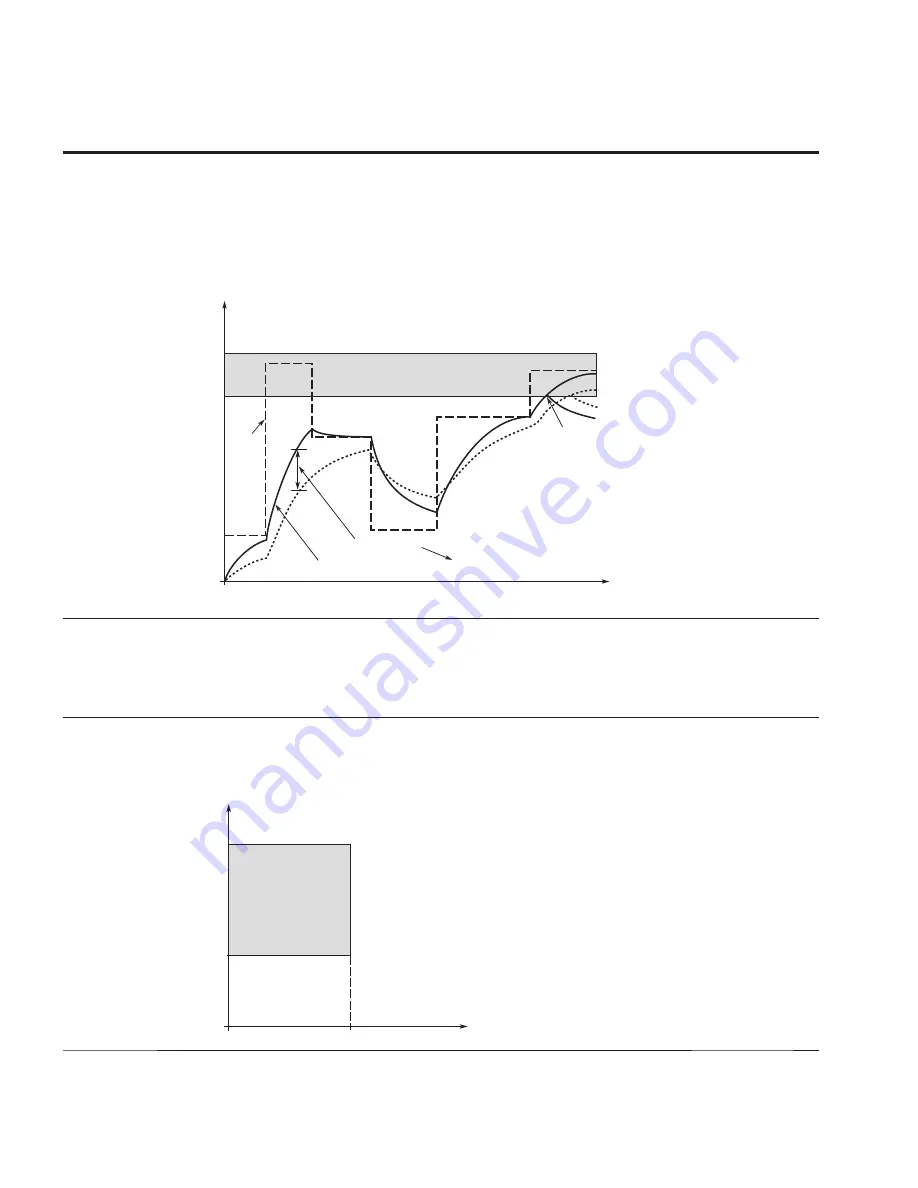
Figure 63. Motor temperature calculation
Time Constant T*
Time
Fault/Warning
P9
.
8
* Changes by motor size and adjusted with P9
.
10
.
Motor Temperature
= (I/IT)2 x (1-e-t/T)
Motor
Current
I/IT
Trip Area
105%
Motor
Temperature
Θ
P6.1.7
313
Stall Protection
1,2,3
RW
Use this parameter to set the device reaction after a “Motor Stalled” condition has occurred. This is
customer selectable based off of current level, frequency level and time.
0 = No Action
1 = Warning
2 = Fault
3 = Fault, Coast
P6.1.8
314
Stall Current Limit
1,2,3
RW
This parameter is used to set the current level when above the unit will stall. For a stall stage to occur, the
current must have exceeded this limit. The software does not allow entering a greater value than In-Motor*2.
If nominal motor current is changed, this parameter is automatically restored to the default value (IL).
Figure 64. Stall characteristics settings
Stall Area
P9
.
12
P9
.
1
4
f
I


