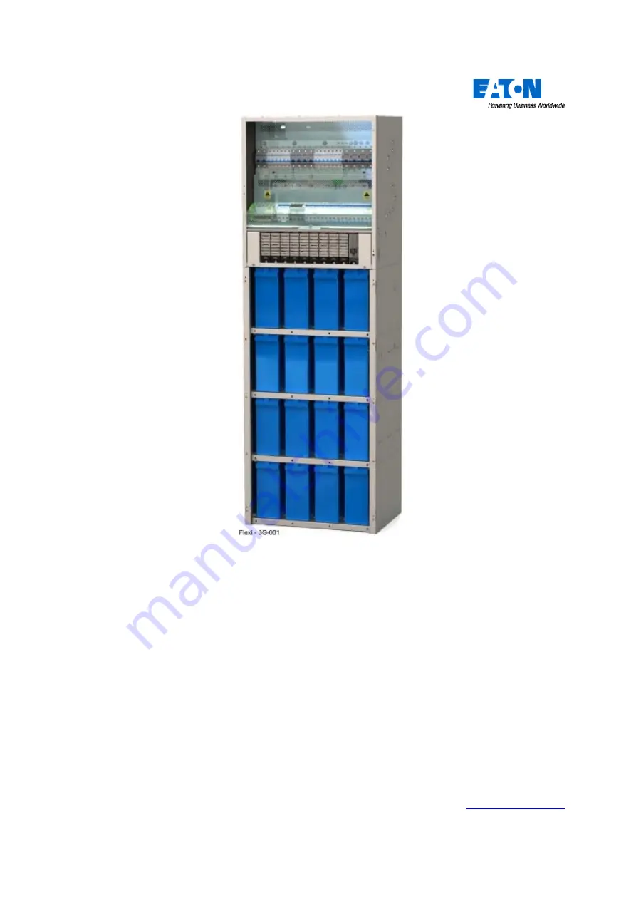
manualshive.com logo in svg
background image

Flexi -3G 

Installation & Commissioning 

Manual 

Document No 4493-CM-EN-10989402 

Issue: 02 

Issue Date: 05 May 2009 

Eaton Corporation

Telecommunications Solutions Division

www.powerware.com


Содержание Flexi-3G

Страница 1: ...xi 3G Installation Commissioning Manual Document No 4493 CM EN 10989402 Issue 02 Issue Date 05 May 2009 Eaton Corporation Telecommunications Solutions Division www powerware com e mail dc info eaton c...

Страница 2: ...pressed or implied Furthermore information contained in this document does not guarantee or imply any ownership of site specific design It is therefore the total responsibility of the installation des...

Страница 3: ...eserved Table of Contents Page No Chapter 1 Introduction 5 Chapter 2 Flexi 3G System General Description 9 Chapter 3 Installation Procedure 19 Chapter 4 Battery Installation 35 Chapter 5 Rectifier Ins...

Страница 4: ...Flexi 3G Installation Commissioning Manual Preface Page 4 of 94 Document No 4493 CM EN 10989402 Copyright 2008 2009 Eaton Corporation All Rights Reserved Page Intentionally Blank...

Страница 5: ...s regarding health and safety refer to document 4493 GD EN 11037101 entitled Installation General Health Safety Guidelines Any health and safety issues directly associated with the task will be found...

Страница 6: ...8 Service Repair RMA Website http epsl powerware com 1 6 Document Numbering For details of document numbering refer to EQP300 1 1 7 Symbols Used in this Document Warnings Advice on hazardous condition...

Страница 7: ...lectrical and electronic equipment This Telecommunications Power Supply System complies with or exceeds the following Standards Electromagnetic Directive EN60950 1 Information Technology Equipment Saf...

Страница 8: ...Flexi 3G Installation Commissioning Manual Chapter 1 Introduction Page 8 of 94 Document No 4493 CM EN 10989402 Copyright 2008 2009 Eaton Corporation All Rights Reserved Page Intentionally Blank...

Страница 9: ...binet Description 11 2 2 1 Battery Cabinet Dimensions 11 2 2 2 Battery Accommodation 12 2 3 Rectifiers 13 2 3 1 Outline Rectifier Technical Specifications 13 2 4 SC200 System Controller 14 2 4 1 Input...

Страница 10: ...2kW Capacity Base Power Box 650H x 600W x 450D 650H x 600W x 450D 650H x 600W x 450D 9 x APR48 3G Capability 9 x APR48 3G Capability 9 x APR48 3G Capability SC200 Controller IOBGP 00 SC200 Controller...

Страница 11: ...nd order The Battery Cabinet is delivered as a flat pack unit and is assembled on site 2 2 1 Battery Cabinet Dimensions Battery Cabinet Rack Type Width mm Depth mm Height mm Battery Cabinet Rack 1150...

Страница 12: ...served 2 2 2 Battery Accommodation Battery Height Accommodation Type 1 Shelf 2 Shelves 3 Shelves 4 Shelves 5 Shelves Rack 1150 1125mm 352mm 352mm 258mm N A Rack 1350 1325mm 419mm 419mm 308mm N A Rack...

Страница 13: ...at up to 70 C 158 F and under a wide range of AC power conditions These features make the APR48 3G perfectly suited to the wide variety of equipment and demanding environmental conditions found in net...

Страница 14: ...page 8 For connector pin outs see document no IPN 997 00012 50 SC200 System Controller Operation Handbook For Troubleshooting regarding the SC200 alarm LEDs see document no IPN 997 00012 50 SC200 Syst...

Страница 15: ...ense inputs XH12 14 DC power system digital inputs 4 pre defined Load Fuse Fail Battery Fuse Fail AC Distribution Fan Fail AC Distribution MOV Fail YH3 Fig 2 7 SC200 I O Board The Alarm Outputs from t...

Страница 16: ...o dc live bus 12 Communications to rectifiers 13 DC power system digital inputs Load Fuse Fail Battery Fuse Fail AC Distribution Fan Fail AC Distribution MOV Fail 14 Connections to battery mid points...

Страница 17: ...AC rating will be dependent upon rectifiers model fitted Rectifier shutdown will occur around 320V but system must withstand input swells up to at least 400V AC without damage 2 6 5 AC Frequency 50 6...

Страница 18: ...Chapter 2 Flexi 3G System General Description Page 18 of 94 Document No 4493 CM EN 10989402 Copyright 2008 2009 Eaton Corporation All Rights Reserved Maximum Discharge Surge Current Imax 8 20 s 40KA E...

Страница 19: ...t Kits per Shelf 22 3 2 4 Parts List for the Optional Door Kit 22 3 2 5 Parts List for the Battery Support Strap Kit 22 3 2 6 Battery Height Accommodation 23 3 3 Assembling the Battery Cabinet 24 3 3...

Страница 20: ...terial This material must be removed once installation is complete 6 The installation area is clean and dry 3 1 2 Positioning No space is necessary at the sides or rear In locating the equipment the f...

Страница 21: ...e Battery Cabinet Quantity Item no Description 1150mm High Cabinet 10945900 1350mm High Cabinet 10946000 1470mm High Cabinet 10953400 1 Side Panel LH 1 1 1 2 Side Panel RH 1 1 1 3 Rear Panel 1 1 1 4 B...

Страница 22: ...vy Washer M5 14 14 N R 17 Nut Full M5 4 4 N R 3 2 3 Parts List for extra Battery Support Kits per Shelf Quantity Item no Description 1150mm High Cabinet 10945900 1350mm High Cabinet 10946000 1470mm Hi...

Страница 23: ...3 Shelves 4 Shelves 5 Shelves Rack 1150 1125mm 352mm 352mm 258mm N A Rack 1350 1325mm 419mm 419mm 308mm N A Rack 1470 1445mm 271mm 271mm 271mm 271mm Qty of 11040200 0 1 2 3 4 Qty of 11040100 0 1 1 2 2...

Страница 24: ...2009 Eaton Corporation All Rights Reserved 3 3 Assembling the Battery Cabinet 3 3 1 Positioning the Side Panels 1 Side Panel LH 2 Side Panel RH Fig 3 2 Positioning the Side Panels 1 With the aid of a...

Страница 25: ...M5 Fig 3 3 Fitting the Rear Panel 1 Put the Rear Panel in position as shown aligning the tabs of the Rear Panel with the slots in the Side Panels 2 Insert the tabs of the Rear Panel into the slots in...

Страница 26: ...ide Panel RH 3 Rear Panel 4 Battery Support Bar Fig 3 4 Fitting the Battery Support Bars 1 Align the tabs on a Lower Battery Support Bar with the punched slots in both of the Side Panels and insert as...

Страница 27: ...aptive Pozi Fig 3 5 Fitting the Battery Support Strap Kit 1 On the Battery Tray second from the bottom if fitted position and secure a set of two Battery Tray Support Straps Slot the end of the straps...

Страница 28: ...ace the Hinge Brackets 3 off in position against the Side Panel RH as shown 2 Secure the Hinge Brackets to the Side Panel RH using the Screws M5x12 CSK Pozi 3 Tighten the Screws M5x12 CSK Pozi to a to...

Страница 29: ...Cabinet Side Panel as shown 2 Insert and lower the Extension Kit Side Panel until it is located 3 Secure the Extension Kit Side Panels to the Cabinet Side Panels using the Screw M5x10 PH Pozi Washer...

Страница 30: ...inet is being secured 1 Place cabinet in position 2 Mark the fixing holes through the base and rear of the cabinet with a permanent marker 3 Remove cabinet 4 Drill all marked holes De burr all holes 5...

Страница 31: ...Washer 5 M5 Plain Washer Fig 3 9 Securing the Power Cabinet to the Battery Cabinet 1 Place the Power Cabinet on top of the Battery Cabinet Note Either a 2 man lift or mechanical aids rated in excess...

Страница 32: ...to the wall after securing it to the Battery Cabinet WARNING The Power Cabinet is not a stand alone unit and must be mounted on top of the Battery Cabinet before attempting to secure it to the wall 1...

Страница 33: ...permanent marker 4 If necessary remove the Power Cabinet from the Battery Cabinet by removing the Power Cabinet to Battery Cabinet Fixings 5 Drill all marked holes De burr all holes 6 Place Power Cab...

Страница 34: ...exi 3G Installation Commissioning Manual Chapter 3 Installation Procedure Page 34 of 94 Document No 4493 CM EN 10989402 Copyright 2008 2009 Eaton Corporation All Rights Reserved Page Intentionally Bla...

Страница 35: ...Page No 4 1 Introduction 36 4 1 1 Battery Accommodation 36 4 2 Installing the Battery Cables 37 4 3 Loading the Battery Shelves 38 4 4 Checking the Batteries 38 4 5 Fitting the Batteries 39 4 5 1 Fitt...

Страница 36: ...for Battery Shelf 2 8 Battery MCB for Optional Battery Shelf 3 9 Battery MCB for Optional Battery Shelf 4 Fig 4 1 Battery Cabinet with Batteries on Battery Shelf 1 only Depending on requirements the...

Страница 37: ...one per battery string to the Ve return bar starting from the RHS of the bar 4 Lay and secure with cable ties the battery loom cables from the appropriate battery shelf up through the cabinet on the R...

Страница 38: ...5 Shelves of Batteries For stability when placing the Power Cabinet onto the Battery Cabinet it is essential to secure the Battery Cabinet to the floor See section 3 4 Securing the Battery Cabinet on...

Страница 39: ...orporation All Rights Reserved 4 5 Fitting the Batteries 4 5 1 Fitting Battery 1 1 Battery Cabinet 2 Battery Shelf 1 3 Battery Shelf 2 6 Battery block1 10 Battery Terminal Cover Fig 4 3 Fitting Batter...

Страница 40: ...9 Eaton Corporation All Rights Reserved 4 5 2 Fitting Battery 2 1 Battery Cabinet 2 Battery Shelf 1 3 Battery Shelf 2 6 Battery 1 7 Battery 2 10 Battery Terminal Cover Fig 4 4 Fitting Battery 2 1 Fit...

Страница 41: ...Rights Reserved 4 5 3 Fitting Batteries 3 4 1 Battery Cabinet 2 Battery Shelf 1 3 Battery Shelf 2 6 Battery 1 7 Battery 2 8 Battery 3 9 Battery 4 10 Battery Terminal Cover Fig 4 5 Fitting Batteries 3...

Страница 42: ...Fixings to the torque recommended by the battery manufacturer The torque for the Link Fixings will be on the battery label 4 Refit the Battery Terminal Covers to Batteries 1 2 5 Remove the left hand B...

Страница 43: ...ery Cables 1 Remove the left hand Battery Terminal Cover from Battery 4 2 Fit the Battery Cable Live Grey ve and secure with the Cable Lug Fixings 3 Tighten the Cable Lug Fixings to the torque recomme...

Страница 44: ...Live Grey ve 15 Battery Cable Common Blue ve Fig 4 8 Replacing the Battery Terminal Covers 8 Refit the Battery Terminal Cover to Battery 1 9 Check with a voltmeter that the negative terminal of batte...

Страница 45: ...tion All Rights Reserved 4 6 Populating Additional Battery Shelves if Required 1 Battery Cabinet 2 Battery Shelf 1 3 Battery Shelf 2 4 Battery Shelf 3 5 Battery Shelf 4 Fig 4 9 2 Battery Shelves Popul...

Страница 46: ...ght 2008 2009 Eaton Corporation All Rights Reserved 1 Battery Cabinet 2 Battery Shelf 1 3 Battery Shelf 2 4 Battery Shelf 3 5 Battery Shelf 4 6 Battery Shelf 5 Fig 4 10 All Battery Shelves Populated 2...

Страница 47: ...orporation All Rights Reserved Chapter 5 Rectifier Installation Table of Contents Topic Page No 5 1 Rectifier Position Numbers 48 5 2 General Notes for Installing a Rectifier 49 5 2 1 Align the Rectif...

Страница 48: ...4 Rectifier Position 4 5 Rectifier Position 5 6 Rectifier Position 6 7 Rectifier Position 7 8 Rectifier Position 8 9 Rectifier Position 9 10 SC200 Controller Fig 5 1 Rectifier Positions in a Rectifier...

Страница 49: ...Red 4 Retaining Screw For details of rectifier alarms see Fault Finding in the SC200 Manual see section 1 3 Related Information on page 5 Fig 5 2 APR48 3G Rectifier I To reduce the risk of electric sh...

Страница 50: ...48 3G Rectifier 3 Rectifier Guide Fig 5 3 Aligning the Rectifier with the Guides 5 2 1 Align the Rectifier with the guides 1 With reference to the installation order given in the tables in sections 6...

Страница 51: ...r 5 Rectifier Installation Document No 4493 CM EN 10989402 Page 51 of 94 Copyright 2008 2009 Eaton Corporation All Rights Reserved 5 2 3 Secure the Rectifier Fig 5 4 Securing the Rectifier 1 Tighten t...

Страница 52: ...Rights Reserved 5 2 4 Fitting Blanking Plates Any slots in the RM10 Rectifier Magazine without rectifiers must have a Blanking Plate fitted This is to ensure optimum airflow through the rectifiers for...

Страница 53: ...off 55 6 3 2 Remove panels if fitted 55 6 3 3 Fit cable 55 6 3 4 Prepare cable 55 6 3 5 Terminate the cable 55 6 3 6 Test 55 6 3 7 Refit panels if required 55 6 4 AC Installation for PBA 01 56 6 4 1 A...

Страница 54: ...tructed with cores to BS6004 class 2 H07V R or similar according to local regulations 6 2 2 AC Wiring Options Refer to the AC Installation section for the Power Box type 6 2 3 AC supply 1 Each phase t...

Страница 55: ...le applying just enough grip to prevent the cable moving Do not over tighten 6 3 4 Prepare cable 1 Strip the individual wires to bare 8mm approx of the conductor 2 Fit appropriate crimps to bare condu...

Страница 56: ...C Installation for PBA 01 6 4 1 AC Connections for PBA 01 15 5 x AC Connectors 16 Earth Connector Fig 6 1 Power Box PBA 01 6 4 2 AC Wiring Options 15 6 x AC Connectors 16 Earth Connector 17 2 way link...

Страница 57: ...Cable Rating 6 4 3 AC Connection Information Fig 6 3 PBA 01 AC Rating Information Label 6 4 4 Installing Rectifiers in a PBA 01 System to Balance Phases In order to provide a balanced load on the inco...

Страница 58: ...nal 15 6 x AC Neutral Connectors 16 Earth Connector 19 Rectifier MCBs Fig 6 4 AC Distribution Panel PBA 02 6 5 1 AC Wiring Option 4 AC 3 Pole Isolator 5 Surge Arrestor Optional 15 6 x Connectors for i...

Страница 59: ...ting Information Label 6 5 3 Installing Rectifiers in a PBA 02 System to Balance Phases In order to provide a balanced load on the incoming AC supply Install the quantity of rectifiers required for th...

Страница 60: ...Rights Reserved 6 6 AC Installation for PBA 03 16 Earth Connector 15 8 x AC Connectors Fig 6 7 AC Distribution Panel PBA 03 6 6 1 AC Wiring Option 15 8 x AC Connectors 16 Earth Connector Fig 6 8 AC C...

Страница 61: ...Rating 6 6 2 AC Connection Information Fig 6 9 PBA 03 AC Rating Information Label 6 6 3 Installing Rectifiers in a PBA 03 System to Balance Phases In order to provide a balanced load on the incoming A...

Страница 62: ...i 3G Installation Commissioning Manual Chapter 6 Installation of AC Cables Page 62 of 94 Document No 4493 CM EN 10989402 Copyright 2008 2009 Eaton Corporation All Rights Reserved Page Intentionally Bl...

Страница 63: ...ion 64 7 1 1 Load MCB s 64 7 1 2 Fitting MCBs 64 7 1 3 De rating factors for Cables and MCBs 64 7 1 3 A MCB Grouping 64 7 1 3 B Temperature de rating for MCBs 64 7 1 3 B i Chint manufactured MCBs 64 7...

Страница 64: ...l with the clip When fitting cables to 25A type MCBs tighten terminals to 2 5Nm When fitting cables to 25A type MCBs tighten terminals to 3 5Nm 7 1 3 De rating factors for Cables and MCBs The followin...

Страница 65: ...C60H Ambient Temp 0 C 10 C 20 C 30 C 40 C De rating Factor 1 05 1 00 0 92 0 86 0 78 Merlin Gerin UL Rated C60N Ambient Temp 0 C 10 C 20 C 30 C 40 C 50 C De rating Factor 1 02 0 97 0 90 0 83 0 76 0 64...

Страница 66: ...ion All Rights Reserved 7 2 Load cable installation 7 2 1 Remove panels if fitted 1 Power Cabinet 2 DC Distribution Cover Insulator Fig 7 1 Power Cabinet 1 Check that the load MCB s being worked on ar...

Страница 67: ...Live L grey Load Cable 3 Cable Clamp Bus bar 4 Return M blue Load Cable 5 Cut out Panel for DC Cable Entry Fig 7 2 Connecting DC Load Cables 1 Remove the appropriate cut outs from the Cut out Panel f...

Страница 68: ...3 Connecting DC Load Cables 1 Terminate the return M blue cable connections to the common busbar using the cable clamps provided Tighten screws to a torque of 2 9Nm 2 Terminate the live L grey cable...

Страница 69: ...69 of 94 Copyright 2008 2009 Eaton Corporation All Rights Reserved Chapter 8 Commissioning Table of Contents Topic Page No 8 1 Introduction 70 8 1 1 Rectifier Configuration 70 8 1 2 Battery Configurat...

Страница 70: ...nd polarity are correct 4 Check that the load connections polarity is correct 8 3 System Start Up 1 Insert 1 APR48 3G Rectifier into the RM10 magazine See Chapter 5 Rectifier Installation on page 47 f...

Страница 71: ...er the following LED s will be lit depending on system configuration Minor Alarm LED Yellow will be lit or Major Alarm LED Red will be lit Multiple Rectifier Fail Refit Rectifiers after test On the SC...

Страница 72: ...Flexi 3G Installation Commissioning Manual Chapter 8 Commissioning Page 72 of 94 Document No 4493 CM EN 10989402 Copyright 2008 2009 Eaton Corporation All Rights Reserved Page Intentionally Blank...

Страница 73: ...x B 2 PBA 01 System Wiring Diagram 76 Appendix B 3 PBA 02 System Wiring Diagram 77 Appendix B 4 PBA 02 System Wiring Diagram 78 Appendix B 5 PBA 03 System Wiring Diagram 79 Appendix C Installation Com...

Страница 74: ...ck 1350 600 450 1350 20 6 Battery Cabinet Rack 1470 600 600 1470 32 7 Optional rack extension kit available to extend rack by 150mm increasing it to 600mm depth thus accommodating deeper batteries Exc...

Страница 75: ...N POS 8 L N RM10 Magazine COMMS RECT GR 1 NOTES GR 1 GREY 70mm TRI RATED UL1284 BL 1 BLUE 70mm TRI RATED UL1284 LARGER CROSS SECTIONS MAY BE USED THROUGHOUT LIVE VE IS GREY GROUND BLUE IF CABLE OR BA...

Страница 76: ...L INPUTS RY6 RY5 RY4 RY3 RY2 RY1 P4 P3 P2 IOBGP 00 2 4 6 5 3 1 7 RMAC1500 00 1 N E 415V 3PH N PE 2 3 OR 230V 1PH N PE ISOLATOR INPUT AC L3 L1 L2 N SURGE MODULE NO NC COM LINK Chassis Earth Stud 0V D1...

Страница 77: ...e COMMS RECT GR 1 NOTES GR 1 GREY 70mm TRI RATED UL1284 BL 1 BLUE 70mm TRI RATED UL1284 LARGER CROSS SECTIONS MAY BE USED THROUGHOUT LIVE VE IS GREY GROUND BLUE IF CABLE OR BARE IF COPPER BAR AUX LVD2...

Страница 78: ...z AC INPUT BR 6 BK 6 GR 6 L1 E E L1 L1 L2 L2 L3 L3 GY 6 24 30 36 20 26 32 21 27 33 22 28 34 23 29 35 BL 6 Blue 6mmSQ TRI RATED UL1015 BR 6 BK 6 GR 6 BL 6 3 19 25 31 3 3 3 3 3 No s 19 to 36 BLACK 6mmSQ...

Страница 79: ...YELLOW 16mm TRI RATED UL1283 GR 4 GREY 70mm TRI RATED UL1284 BL 4 BLUE 70mm TRI RATED UL1284 LARGER CROSS SECTIONS MAY BE USED THROUGHOUT LIVE VE IS GREY GROUND BLUE IF CABLE OR BARE IF COPPER BAR AUX...

Страница 80: ...CABINET SYSTEM TYPE Flexi 3G RACK DESIGNATION FLOOR UNIT SUITE MANUFACTURER Eaton SERIAL NO DELIVERY DATE IN SERVICE DATE ALARM MANAGEMENT SYSTEM TYPE SC200 MOD REV LEVEL MANUFACTURER Eaton NETWORK A...

Страница 81: ...is used for AC Protective Earth Y N Correct cable and size are used for Clean Earth If applicable Y N All terminations are secured to correct torque Y N AC input conductors are sized and terminated c...

Страница 82: ...harge Y N Record battery current A V System I P configuration is appropriate for and correctly configured for the mains supply Y N V V Record AC supply voltages V Check Analogue measurements as requir...

Страница 83: ...pendices Document No 4493 CM EN 10989402 Page 83 of 94 Copyright 2008 2009 Eaton Corporation All Rights Reserved Appendix D Monobloc Test Record 12V Monobloc 48V String Block Number Open Circuit Volta...

Страница 84: ...used when carrying out a battery discharge tests in the event of a suspected battery fault Building Name System Type Flexi 3G Rack Designation Floor Unit Suite At 5 Minutes At End Of Discharge Batter...

Страница 85: ...oor Unit Suite RECTIFIERS Recovered Replacement Rectifier Rectifier No Serial No Type Rating Manufacturer Serial No Mod Rev Level Date of Change BATTERIES MONOBLOCS Number of Recovered battery monoblo...

Страница 86: ...402 Copyright 2008 2009 Eaton Corporation All Rights Reserved Appendix G Routines Faults Record SYSTEM Building Name System Type Flexi 3G Rack Designation Floor Unit Suite ROUTINES AND FAULTS Routines...

Страница 87: ...n Essential Non Essential No of Ways Rating A No of Phases Fuse Way Fuse Rating A Cable Size mm CPC Size mm Trunking Material Trunking Width x Depth x mm Orientation Fill Factor Measured Ambient Tempe...

Страница 88: ...ctrical installation before working on this equipment Equipment Code Number Conductor Continuity Insulation Resistance RCD Ring Final Circuits P H A S E W A Y CPC and Bonding P N PE N or L1L2L3 E N M...

Страница 89: ...opyright 2008 2009 Eaton Corporation All Rights Reserved Site Built Assembly Test Engineer Name Mechanical Protection Flash Test Test Engineer Signature IP2X IP4X PASS Applied Volts Pass Company Name...

Страница 90: ...imary check dead link primary phases neutral link DC live return Insulation DC AC M Insulation DC Earth M Links removed and supply restored DC Cables those installed as part of this job only Load Cct...

Страница 91: ...Manual Chapter 9 Appendices Document No 4493 CM EN 10989402 Page 91 of 94 Copyright 2008 2009 Eaton Corporation All Rights Reserved EFLI PSSC Equipment Type MIN MAX MIN MAX NOTES EFLI PSSC measured at...

Страница 92: ...our signatures below particulars of which are described above have exercised reasonable skill and care when carrying out the construction hereby CERTIFY that the construction work for which I we have...

Страница 93: ...e Certificate Details of Installation Earth Electrode where applicable Type e g rod s tape Location Electrode resistance R A Means of Earthing Supplier s facility Installation Earth Electrode Maximum...

Страница 94: ...f discharge of Energy Separation of category 3 cables b Protection against direct contact Insulation of live parts xi Presence of undervoltage protective devices where appropriate Barriers or enclosur...

Отзывы: