Page 14
7.0 AUXILIARY POWER MODULE
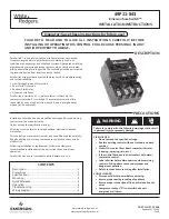
The Auxiliary Power Module or APM (Cat No.
PRTAAPM), illustrated in Fig.
7,
is an encapsulated
power supply that requires a
120
Vac input at either
5 0
or
60 Hz. It provides an output of 32 Vdc (nominal 40 Vdc
open circuit) which can be used for testing a Digitrip RMS
5 10
Trip Unit.
When a drawout circuit breaker is equipped with a Dig
itrip RMS
5 10
Trip Unit, it can be conveniently set and
tested while the circuit breaker is out of its cell or in its
cell in the "Test", "Disconnect" or "Withdrawn" positions
by using the Auxiliary Power Module.
The Auxiliary Power Module is equipped with a unique
plug-in connector suitable only for plugging into the
keyed receptacle in the upper right corner of a Digitrip
RMS Trip Unit as shown in Fig.
1.
This prohibits the pos
sible use of an incorrect type power module.
8.0 FRAME RATINGS, (WHERE APPLICABLE,
SENSOR RATINGS) AND RATING PLUGS
The
Frame Rating
of a circuit breaker is the maximum
RMS current it can carry continuously. The maximum
Short-Circuit Current Rating of the Circuit breaker are
usually related to the Frame Rating as well.
It is often times desirable to be able to choose a current
value (In), less than the full frame rating, to be the basis
for the coordination of the circuit breaker's protection
functions, without affecting its short-circuit current capa
bility. For the Digitrip
5 10
trip unit this is implemented by
changing the
Rating Plug
(and/or
Current Sensors,
where applicable - See your circuit breaker instructions
(listed in Section 9.0 below) to determine if this applies to
your circuit breaker).
The
(Current) Sensor Rating
(where applicable) is the
maximum RMS current the circuit breaker can carry with
the specified current sensors installed. The Sensor Rat
ing can be the same or less than the Frame Rating, but
not greater.
The
Rating Plug
(See Fig. 6) fits into a special cavity to
complete the trip unit (See Fig.
1).
Rating plugs have two
current ratings listed on their covers (See Fig. 6):
1)
the "Must be used with Frame Rated" cur
rent value (or "Sensor Rated", if applica-
I.L. 29-8858
ble),
and 2)
"In
(Rated I)
="
current value.
This latter value, (In) is the basis for the trip unit current
settings:
1)
2)
The Instantaneous and Ground Current
Settings (if provided) are multiples of (In)
(See Sections 4.6 and 4.8)
The Long Delay Current Setting,
Ir ,
is a
multiple of (In). Long Delay Current Setting
=
Ir
=
LD x (In). (See Section 4.2)
3)
The Short Delay Current Setting (if pro
vided) is indirectly dependent upon (In),
because it is a multiple of
Ir,
which in turn
is a multiple of (In).
Short Delay Current Setting
=
SD x
Ir
=
SD x LD x (In).
(See Section 4.4)
Rating Plugs for the Digitrip RMS
5 10
trip units are
marked for and may be applied on both
5 0
and 60 Hz
systems.
A
CAUTION
BEFORE YOU FIT THE RA TING PLUG INTO THE TRIP
UNIT,
BE SURE TO
CHECK
THAT THE
BREAKER
TYPE
AND
FRAME RA TlNG
(OR
SENSOR RA TING
IF
APPLICABLE),
MA TCH
THOSE PRINTED ON THE
RA TlNG PLUG
COVER.
INSTALLING A RA TlNG
PLUG THA T DOES NOT MATCH THE BREAKER
TYPE AND FRAME RA TlNG (OR SENSOR RA TlNG, IF
APPLICABLE), CAN PRODUCE SERIOUS MISCOOR
DINATION ANDIOR FAILURE OF THE PROTECTION
SYSTEM.
Complete catalog descriptions of all available rating
plugs are given in the applicable circuit breaker supple
mentary instruction leaflets. (See Section
9)
Note: Rating plugs from Digitrip models 500/600/7001
800 CAN NOT be used with model 51 0 trip units. The
connection pins are located in different positions, so
that one cannot aCCidentally use the incorrect kind of
plug.
Effective May 1997
www
. ElectricalPartManuals
. com
Содержание Digitrip RMS 510 LI
Страница 17: ...I L 29 8858 Page 17 NOTES Effective May 1997 w w w E l e c t r i c a l P a r t M a n u a l s c o m...
Страница 18: ...Page 18 I L 29 8858 NOTES Effective May 1997 w w w E l e c t r i c a l P a r t M a n u a l s c o m...
Страница 19: ...I L 29 8858 Page 19 NOTES Effective May 1997 w w w E l e c t r i c a l P a r t M a n u a l s c o m...