I.B. 48003
Page 20
Effective 11/97
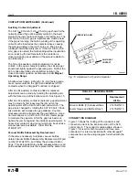
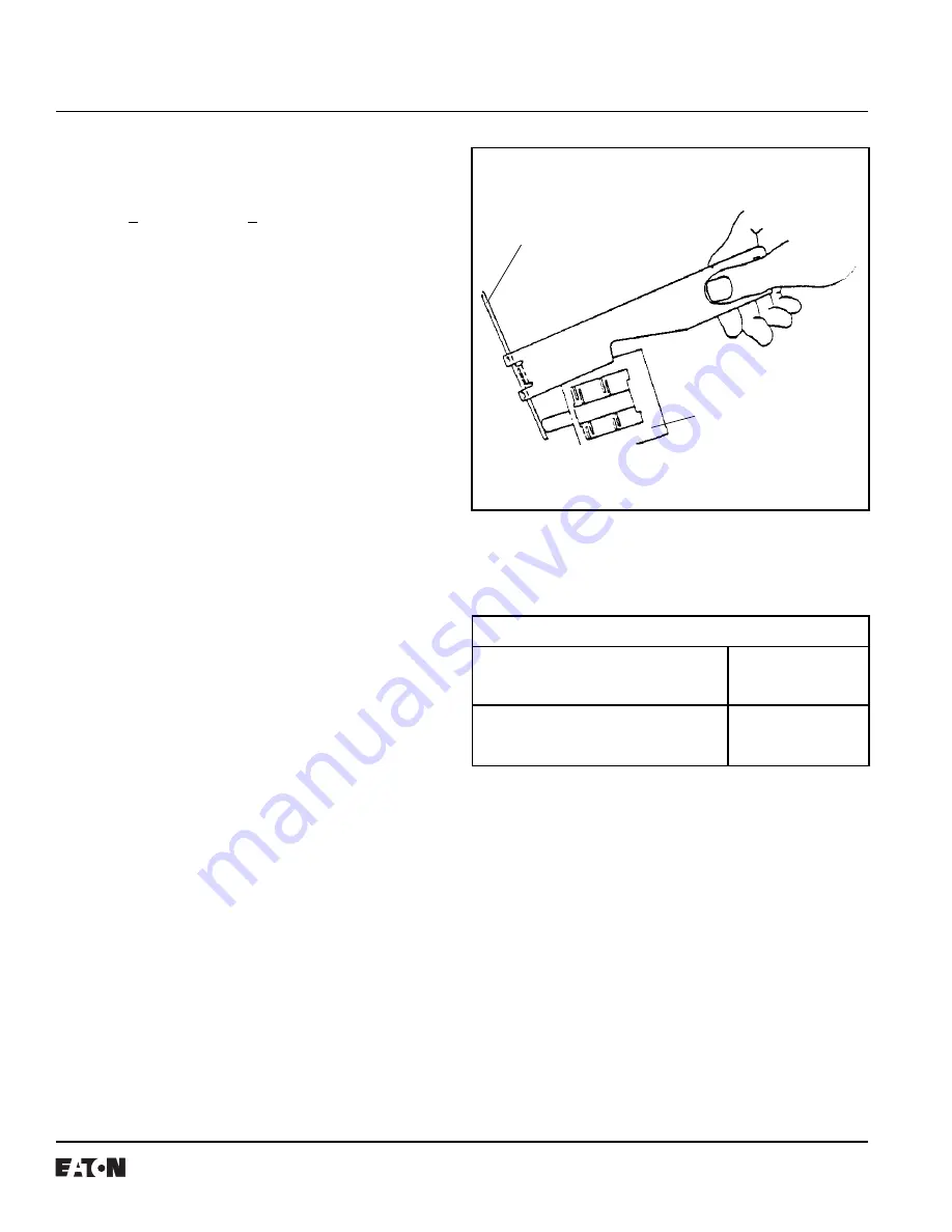
OPERATING ARM
BOTTLE WRENCH
AUXILIARY
CONTACT
CONTACTOR MAINTENANCE (Continued)
Auxiliary Contact Adjustment
The 0.410 + .010-inch (10.4 + .25-mm) gap shown for the
normally-closed Type L63 auxiliary contact in the insert
picture in the lower portion of Figure 12 is factory set. The
0.410-inch (10.4-mm) gap is important and must be held.
If the gap is too large, the hold-in winding of the operating
coil will not be inserted as the contactor closes, causing
the pick-up winding in the coil to burn out. The pick-up
winding is intermittent-duty rated. If the 0.410-inch (10.4-
mm) gap is too small, the hold winding will be inserted too
soon, reducing the pull force before the contactor is
closed, producing an oscillation of the armature similar to
an old doorbell.
The Type L64 auxiliary contact adjustment is not as
critical. In the open-contactor position, the L64 plunger
should rest lightly against the operating arm. Neither the
L63 or L64 assemblies should bottom solidly in the
closed contactor position, as discussed under Magnet
Operating Range.
A bottle wrench and a .020-inch (.51-mm) feeler gauge
are screw mounted to the right-hand sidesheet of the
contactor when the Amgpard
®
controller is shipped.
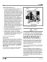
After an L64 auxiliary contact is added or replaced,
adjustment can be made by bending the operating arm
with the forked end of the bottle wrench. See Figure 15.
After an L63 auxiliary contact is replaced, gap adjustment
may be made by first loosening the jam nut on the
operating arm with a 0.438-inch open-end wrench. The
gap size is changed by rotating the 0.25"-20 bolt. Clock-
wise rotation will increase the gap distance. Counter-
clockwise rotation will decrease the gap distance. Use a
Vernier calipers or a 0.410-inch (10.4-mm) feeler gauge
to measure the gap size. After the gap has been set,
tighten the jam nut against the interlock operating arm. A
heavy-duty contactor closing tool which can be used as a
manual operator is available. Order Part No.
2147A47G17.
Vacuum Bottle Subassembly Replacement
If it becomes necessary to replace vacuum bottles,
obtain Vacuum Bottle Subassembly Replacement Kit part
number 2147A47G13, and follow the enclosed instruc-
tions. This kit includes three bottle subassemblies, as all
bottle subassemblies must be replaced at the same time.
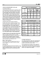
TABLE V - RENEWAL PARTS
Replacement
Item
Kit No.
Vacuum Bottle (3) Subassemblies
2147A47G13
Feeler Gauge and Bottle Wrench
2147A47G15
Fig. 15 Adjustment of Type L64 Operator
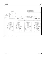
CONNECTION DIAGRAM
Figure 17 shows the routing of the conductors and
connection points to the internal portion of the SJS
control circuit. The conductor cable pattern shown in
Figure 17 is used for both two-pole and three-pole
contactors. For interconnections with other Ampgard
®
components, see the wiring diagram furnished with the
order.
5259C37
Содержание Cutler-Hammer Ampgard SC9000
Страница 3: ...I B 48003 Page 3 Effective 11 97 Fig 4 Ampgard Components Two Starters Controllers Shown ...
Страница 9: ...I B 48003 Page 9 Effective 11 97 Fig 11 Type SJS Contactor Positions ...
Страница 21: ...I B 48003 Page 21 Effective 11 97 Fig 16 Cable and Connection Diagram ...
Страница 24: ...I B 48003 Page 24 Effective 11 97 Printed in U S A CCI Cutler Hammer 221 Heywood Road Arden NC 28704 ...

