I.B. 48003
Page 11
Effective 11/97
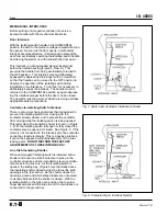
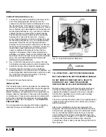
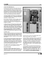
When there is access space behind the installation, the
rear panel of the enclosure can be removed to facilitate
wiring. Adequate space has been provided at the rear of
the enclosure for medium-voltage line and load cables,
while low-voltage cables may be conveniently arranged
near the right-hand enclosure wall. See Figure 3.
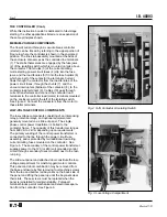
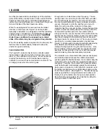
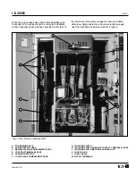
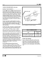
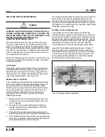
G. ISOLATING SWITCH
H. ISOLATING SWITCH AUXILIARY CONTACT TERMINAL BLOCKS
J.
ISOLATING SWITCH MECHANICAL INTERLOCK
K. FUSE PULLER
L. LOAD CABLES
M. MOTOR TERMINALS
A. POSITIONING BOLTS
B. POWER CIRCUIT FUSES
C. MEDIUM-VOLTAGE COMPARTMENT DOOR
D. CONTROL TERMINAL BLOCKS
E. VACUUM CONTACTOR
F.
LOW-VOLTAGE COMPARTMENT DOOR
A
D
F
J
K
L
C
M
G
Fig. 13 Key Points In Disassembly
E
H
B
Содержание Cutler-Hammer Ampgard SC9000
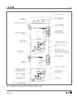
Страница 3: ...I B 48003 Page 3 Effective 11 97 Fig 4 Ampgard Components Two Starters Controllers Shown ...
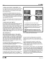
Страница 9: ...I B 48003 Page 9 Effective 11 97 Fig 11 Type SJS Contactor Positions ...
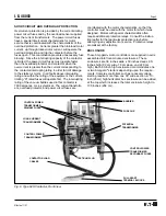
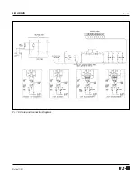
Страница 21: ...I B 48003 Page 21 Effective 11 97 Fig 16 Cable and Connection Diagram ...
Страница 24: ...I B 48003 Page 24 Effective 11 97 Printed in U S A CCI Cutler Hammer 221 Heywood Road Arden NC 28704 ...


