I.B. 48003
Page 13
Effective 11/97
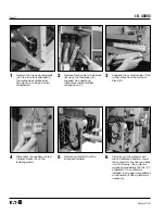
9
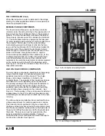
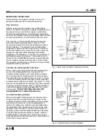
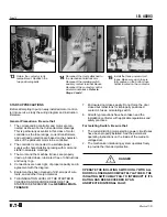
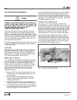
If no vertical bus bars are present
and cable is used to connect
power to the line stabs, loosen
four pan head screws holding the
barrier and shutter assemble
approximately three turns. Lift the
assembly up and off the screws.
Disconnect the shutter drive lever
using the keyhole in the lever.
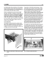
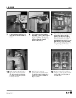
7
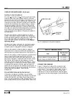
Free the isolating switch (H), by
removing two hex head bolts as
shown.
10
Refer to load cable instruction
tag located at motor terminals
(M) for load wiring instructions.
Controller is now ready to wire,
both line and load.
11
After wiring, reverse the
procedure to reassemble. Slide
the isolating switch in place and
secure with two bolts. Refer to
Steps 7 and 8.
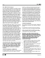
12
Check to make sure each fuse
clamp is in correct position in fuse
locator. Refer to instructions on
the lower door.
8
Pull the isolating switch forward.
CAUTION: It has no latch and will
pull completely out. However, it
weighs only 75 lbs. (34 kilograms)
and can usually be handled
without a crane or lift.
Содержание Cutler-Hammer Ampgard SC9000
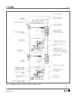
Страница 3: ...I B 48003 Page 3 Effective 11 97 Fig 4 Ampgard Components Two Starters Controllers Shown ...
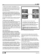
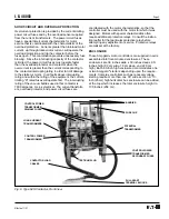
Страница 9: ...I B 48003 Page 9 Effective 11 97 Fig 11 Type SJS Contactor Positions ...
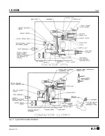
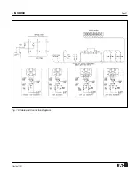
Страница 21: ...I B 48003 Page 21 Effective 11 97 Fig 16 Cable and Connection Diagram ...
Страница 24: ...I B 48003 Page 24 Effective 11 97 Printed in U S A CCI Cutler Hammer 221 Heywood Road Arden NC 28704 ...


