


UPS SYSTEM INSTALLATION
Eaton 9395 Plus 1 UPS (225–275 kVA) Installation and Operation Manual
S
164201710 Rev 2
www.eaton.com\powerquality
4-15
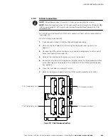
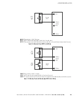
4.5.3
Battery Power Wiring
C
A
U
T
I
O
N
When sizing the battery system, do not exceed the internal battery charger capabilities. See Chapter 10,
“Product Specifications,” for maximum battery charger currents.
To install wiring to connections:
1.
If using an Eaton battery cabinet, proceed to Step 2; otherwise, proceed to
Step 4.
2.
Route and connect the battery cables between the UPS and battery cabinet or
battery disconnect according to the instructions in the
Eaton 9395 Integrated
Battery Cabinet (Model IBC-L) Installation Manual
, listed in paragraph 1.8 on
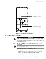
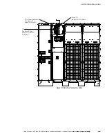
page 1-9. See Figure 4‐4 and Figure 4‐6 for wiring access information and
terminal locations.
3.
Proceed to Step 5.
4.
Route and connect the battery cables between the UPS and battery system or
battery disconnect. See Figure 4‐4 and Figure 4‐6 for wiring access information
and terminal locations.
5.
If wiring the UPS for a common battery, proceed to Step 6; if wiring for a
separate battery, proceed to Step 8.
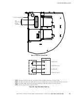
6.
Connect the positive, negative, and ground DC power wiring from the battery
cabinet or disconnect to the UPS cabinet battery and ground terminals. Use both
sets of terminals shown in Figure 4‐11 as needed. See paragraph 3.2.2 on
page 3-6 for wiring and termination requirements.
7.
Proceed to Step 9.
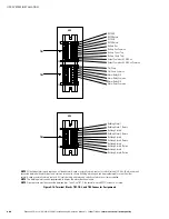
8.
Connect the positive, negative, and ground DC power wiring from the battery
cabinets or disconnects to the UPS cabinet battery and ground terminals. Use
one set of terminals for each UPM as shown in Figure 4‐12. See paragraph 3.2.2
on page 3-6 for wiring and termination requirements.
9.
After wiring the UPS system to the facility power and critical load, be sure to
ground the system according to local and/or national electrical wiring codes.
10.
If wiring interface connections, proceed to paragraph 4.6; otherwise, proceed to
Step 11.
11.
When all wiring is complete, reinstall the safety shield panel removed in
paragraph 4.5.2, Step 2 on page 4-7. Secure with the retained hardware.
12.
Reinstall the left front panel removed in paragraph 4.5.2, Step 1 on page 4-7 and
secure with the retained hardware.
Содержание 9395 Plus 1
Страница 1: ...Powerware Series Eaton 9395 Plus 1 UPS 225 275 kVA Installation and Operation Manual ...
Страница 2: ......
Страница 3: ...Powerware Series Eaton 9395 Plus 1 UPS 225 275 kVA Installation and Operation Manual ...
Страница 185: ......
Страница 186: ... 1642017102 164201710 2 ...