background image

1027212

UPS 225 - 275 kVA/300kVAPF0.8

75

Revision E

User’s and Installation Guide

Service History

The Service History Log is for service personnel and is password protected. 
If the customer needs access to the log, contact an Eaton service represen-
tative. Press the SERVICE pushbutton on the User History menu bar to dis-
play the Service History Log. The Service History Log lists up to 2048 
events in chronological order, with the most recent event listed last (once 
2048 is reached, the earliest event is overwritten). The end of the log (the 
most recent events) is displayed first; scroll upward to view older event 
listings. To scroll through the events, press the up or down arrow pushbut-
ton on the menu bar. To return to the User History screen, press the USER 
pushbutton on the menu bar. To return to the Active Events screen, press 
the EVENTS pushbutton on the menu bar.
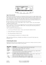
Meters - UPS
Meters - UPM

The Meter screens show the UPS meter readings for the unit. The default 
voltage displayed on these screens is phase-to-neutral. However, an autho-
rized Eaton Customer Service Engineer can change the screens to display 
the voltage phase-to-phase (L1-L2, L2-L3, L3-L1). Press the METERS push-
button on the main menu bar to display the Meter screens. To scroll 
through the meter screens, press the up or down arrow pushbutton on the 
menu bar. The current UPS readings are displayed in the information area 
of the screen.

Output - UPS
Output - UPM

The Output screen shows output voltage (phase-to-neutral), output current 
(each phase), and frequency being supplied by the UPS, as well as the kVA, 
kW, and power factor measurements.

Input - UPS
Input - UPM

The Input screen shows input voltage (phase-to-neutral), input current 
(each phase), and frequency of the incoming utility source, as well as the 
kVA, kW, and power factor measurements.

Bypass

The Bypass screen shows the bypass input voltage (phase-to-neutral), 
input current (each phase), and frequency of the incoming utility source, as 
well as the kVA, kW, and power factor measurements.

Battery - UPS
Battery - UPM

The Battery screen displays the battery voltage (Vdc), the battery current 
(Idc), the minutes of battery time remaining, and battery temperature. Bat-
tery temperature must be set up by an authorized Eaton Customer Service 
Engineer. When battery life decreases to less than 20%, Check Battery is 
displayed.

Statistics

The Statistics screen displays the hours on line and the total kW hours 
used.

Output Current - UPS
Output Current -UPM

The Output Current screen displays a real-time bar graph of the output cur-
rent of the UPS. The graph shows the current for each phase.

Output Power - UPM

The Output Power screen displays the power in kW and kVA for each UPM.

System Level 0 
Setup

Function Selection

This screen can be used to set the screen contrast, show the firmware ver-
sions installed, identify the unit type, change the display language, set up 
Energy Saver functions, set up Advanced Power Management functions, 
and enter a password to access Level 1 functions.
Press the SETUP pushbutton on the main menu bar to display the System 
Setup Level 0 Screen. No password is necessary to access Level 0 func-
tions. Use the up or down arrow pushbutton to highlight the setup function 
screen desired, then press the SELECT pushbutton to display the function 
screen.

Function

Subfunction

Operation

Содержание 9395-275

Страница 1: ...Eaton 9395 UPS 225 275 kVA 300kVAPF0 8 User s and Installation Guide...

Страница 2: ...and industrial application in the second environment Installation restrictions or additional measures may be needed to prevent disturbances 2010 Eaton Corporation All Rights Reserved The contents of...

Страница 3: ...ring preparation 21 3 3 Inspecting and unpacking the UPS cabinet 22 4 UPS system installation 24 4 1 Preliminary installation information 24 4 2 Unloading the UPS cabinet from the pallet and mechanica...

Страница 4: ...7 3 18 Transfer from Energy Saver System to Bypass mode 90 7 3 19 Transfer from Bypass to High Alert mode 90 7 3 20 Transfer from High Alert to Bypass mode 91 7 3 21 Transfer from Energy Saver System...

Страница 5: ...off Switch 113 8 Communication 115 8 1 X Slot cards 115 8 2 LanSafe Power Management Software 115 8 3 Terminal mode 116 8 3 1 Display UPS control panel 116 8 3 2 Event History Log 116 8 4 Building ala...

Страница 6: ...arts not supplied by Eaton Corporation 18 Table 3 7 Recommended input circuit breaker ratings 18 Table 3 8 Recommended bypass and output circuit breaker ratings 18 Table 3 9 Recommended DC input circu...

Страница 7: ...e Card 45 Figure 5 2 HotSync CAN Bridge Card connections 46 Figure 5 3 Distributed bypass system CAN and Pull Chain simplified interface wiring 48 Figure 5 4 Distributed bypass system UPS CAN wiring w...

Страница 8: ...ii UPS 225 275 kVA 300kVAPF0 8 1027212 User s and Installation Guide Revision E...

Страница 9: ...d operation The UPS system is housed in a single free standing cabinet with safety shields behind the door for hazardous voltage protection The cabinet matches the battery and distribution cabinets in...

Страница 10: ...PS 225 275 kVA 300kVAPF0 8 1027212 User s and Installation Guide Revision E Figure 1 1 Eaton 9395 UPS 225 275 kVA 300kVA cabinet Figure 1 2 Eaton 9395 UPS 225 275 kVA 300kVA typical single module syst...

Страница 11: ...imizing recharge time and protects batteries from damage due to high current charging and inverter ripple currents Charging at high currents can overheat and damage batteries 1 1 5 Power Management So...

Страница 12: ...UPSs and a customer supplied tie cabinet or load distribution panel to act as a tie point The tie cabinet must contain Module Output Breakers MOBs with dual auxiliary contacts for control of the syst...

Страница 13: ...ble Module Management System and Energy Saver System modes are mutually exclusive The Variable Module Management System VMMS mode maintains UPM redundancy and achieves higher efficiencies by intellige...

Страница 14: ...allation and operation In particular be thoroughly familiar with the REPO procedure see Section Using the Remote Emergency Power off switch on page 95 The information in this manual is divided into se...

Страница 15: ...ocal service representative if help is needed with any of the following Scheduling initial startup Regional locations and telephone numbers A question about any of the information in this manual A que...

Страница 16: ...ve humidity 95 maximum The system is not intended for outdoor use Ensure all power is disconnected before performing installation or service Batteries can present a risk of electrical shock or burn fr...

Страница 17: ...N and WARNING notices affixed to the inside and outside of the equipment CAUTION To prevent damage to the wiring channel and wiring in the UPS cabinet base when lifting or moving the cabinet Lift and...

Страница 18: ...ms specified on page 124 become void This service is offered as part of the sales contract for the UPS Contact service in advance usually a two week notice is required to reserve a preferred startup d...

Страница 19: ...S cabinets use forced air cooling to regulate internal component temperature Air inlets are in the front of the cabinet and outlets are in the top You must allow clearance in front of and above each c...

Страница 20: ...tilation requirements during full load operation Ventilation required for cooling air exhaust approximately 900 liter sec 225 275kVA unit 260 liter sec ISBM Figure 3 1 UPS cabinet dimensions front vie...

Страница 21: ...1027212 UPS 225 275 kVA 300kVAPF0 8 13 Revision E User s and Installation Guide Figure 3 2 UPS cabinet dimensions right side view Figure 3 3 UPS cabinet dimensions top view...

Страница 22: ...14 UPS 225 275 kVA 300kVAPF0 8 1027212 User s and Installation Guide Revision E Figure 3 4 UPS cabinet dimensions bottom view Figure 3 5 UPS cabinet dimensions bottom view with mounting brackets...

Страница 23: ...1027212 UPS 225 275 kVA 300kVAPF0 8 15 Revision E User s and Installation Guide Figure 3 6 UPS cabinet center of gravity Figure 3 7 Remote EPO switch dimensions...

Страница 24: ...ypass wiring data is not applicable to Input Output Module IOM configurations Table 3 4 Input output ratings and external wiring requirements for the Eaton 9395 275 225 9395 275 275 and 9395 300 Units...

Страница 25: ...r remove the shield before operating the UPS Once the debris shield is removed do not place objects on the ventilation grill Terminals E1 through E12 are 2 hole bus bar mountings See Table 3 5 for pow...

Страница 26: ...d as if supplying a 275 300 kVA three phase transformer to allow for inrush current Bypass input wiring and bypass input breaker rating should be treated as if supplying a 275 300 kVA load regardless...

Страница 27: ...duty rated circuit breakers satisfying the criteria for both Table 3 9 Recommended DC input circuit breaker ratings Rated battery current is computed at 1 7 volts per cell The battery wiring used betw...

Страница 28: ...nected between the alarm input and common terminal All control wiring and relay and switch contacts are customer supplied Use twisted pair wires for each alarm input and common The building alarms can...

Страница 29: ...n page 16 The UPS can be installed in a high resistance ground application only by using a factory installed neutral forming kit MOBs with dual auxiliary contacts are to be provided by the customer Ta...

Страница 30: ...installation site or as close as possible before unpacking Insert the forklift or pallet jack forks from the right side of the cabinet between the supports on the bottom of the pallet see Figure 3 6...

Страница 31: ...tion Guide NOTE While waiting for installation protect the unpacked cabinet from moisture dust and other harmful contaminants Failure to store and protect the UPS properly may void your warranty Figur...

Страница 32: ...he UPS 4 2 Unloading the UPS cabinet from the pallet and mechanical installation The UPS cabinet is bolted to a wooden pallet supported by wood skids To remove the pallet and mechanically install the...

Страница 33: ...the cabinet retain the shipping bracket and securing hardware for later use 3 Remove the three bolts securing the right side shipping bracket to the cabinet and three bolts securing the bracket to the...

Страница 34: ...26 UPS 225 275 kVA 300kVAPF0 8 1027212 User s and Installation Guide Revision E Figure 4 1 Removing left side shipping bracket Figure 4 2 Removing right side shipping bracket...

Страница 35: ...installed proceed to Section 4 5 if installing a distributed bypass tie cabinet otherwise proceed to Section 4 6 to complete the wiring of the UPS and battery cabinet 4 5 Distributed bypass tie cabine...

Страница 36: ...ode For proper operation the following must be true 1A 2A 3A 4A 1B 2B 3B 4B In order to save cabling costs the following is also considered to be sufficient 1A 1B 2A 2B 3A 3B 4A 4B Any difference in w...

Страница 37: ...ions 1 Remove one top screw and two bottom screws securing the UPS left front panel see Figure 4 2 on page 26 Lift the panel straight up to remove from the panel hanger bracket at the top of the cabin...

Страница 38: ...30 UPS 225 275 kVA 300kVAPF0 8 1027212 User s and Installation Guide Revision E Figure 4 4 Conduit and wire entry locations...

Страница 39: ...1027212 UPS 225 275 kVA 300kVAPF0 8 31 Revision E User s and Installation Guide Figure 4 5 UPS power terminal locations See Figure 4 6 for detail AA Figure 4 6 UPS power terminal detail AA...

Страница 40: ...C power wiring from the battery cabinet to the UPS cabinet battery and ground terminals See Section 3 2 2 on page 16 for wiring and termination requirements 4 Proceed to Step 7 5 Route and connect the...

Страница 41: ...ve it from the panel hanger bracket at the top of the cabinet 6 Remove the screws securing the protective cover panel and remove the panel Retain the hardware for later use 7 Terminal block TB3 is acc...

Страница 42: ...and secure with the retained hardware Figure 4 7 Typical alarm relay connection NOTE Alarm relay contacts have a maximum current rating of 5A and a switched voltage rating of 30 Vac and 28 Vdc Alarm...

Страница 43: ...Revision E User s and Installation Guide Figure 4 8 Interface terminal locations NOTE For TB1 TB2 and TB3 connector assignments see Figure 4 10 and for detail AA see Figure 4 9 The X Slot communicati...

Страница 44: ...10 Terminal blocks TB1 TB2 and TB3 connector assignments NOTE All building alarm inputs require an isolated normally open or normally closed contact or switch rated at 24 Vdc 20 mA minimum connected b...

Страница 45: ...PO NO 4 Remote EPO return 5 Battery aux 6 Battery aux return 7 48 Vdc battery shunt trip 8 48 Vdc battery shunt trip 9 K3 AUX 10 K3 AUX return Terminal TB2 Name Description 1 Pull chain Backup control...

Страница 46: ...the UPS cabinet interface entry plates to drill or punch holes see Figure 4 4 on page 30 10 Reinstall the interface entry plates 11 If battery cabinets are installed attached to the UPS cabinet procee...

Страница 47: ...stallation and setup of an X Slot card please contact Eaton Corporation To install wiring to connections 1 If not already installed install the LAN and telephone drops 2 Unfasten the front door latch...

Страница 48: ...40 UPS 225 275 kVA 300kVAPF0 8 1027212 User s and Installation Guide Revision E Figure 4 12 X Slot communication bays...

Страница 49: ...t the door off Retain the hardware for later use 5 If installing interface wiring through the left interface entry conduit landing proceed to Step 6 otherwise proceed to Step 8 6 If not already accomp...

Страница 50: ...d 7 of the remote EPO switch where applicable as shown in Figure 4 13 Remote EPO switch wiring must be in accordance with electrical code requirements 16 When all wiring is complete reinstall the prot...

Страница 51: ...nimum Remote EPO normally open and normally closed return terminals are separated on the terminal board but are connected together Figure 4 16 Normally closed and normally open remote EPO switch wirin...

Страница 52: ...t the end of this manual This checklist ensures that you have completely installed all hardware cables and other equipment Complete all items listed on the checklist to ensure a smooth installation Ma...

Страница 53: ...rned off and all power sources are disconnected See Chapter 7 UPS operating instructions for shutdown instructions 2 Unfasten the front door latch and swing the door open see Figure 4 2 on page 26 3 I...

Страница 54: ...l Name Description 1 Alarm Programmable UPS alarm Activate by a remote dry contact closure 2 Alarm Return 3 Alarm Relay NC Normally closed contact opens when UPS is on bypass 4 Alarm Relay Com Bypass...

Страница 55: ...ination requirements see Section 3 2 3 on page 20 Table 4 1 on page 38 and Figure 4 8 on page 35 through Figure 4 10 7 Route and install CAN wiring between the UPS cabinets See Figure 5 2 and Table 5...

Страница 56: ...can be placed in any physical order Figure 5 4 Distributed bypass system UPS CAN wiring without MOBs NOTE External CAN connections between UPSs require shielded twisted pair wire Table 5 2 CAN Bridge...

Страница 57: ...ing without MOBs NOTE Use twisted pair wiring between the UPS and MOB AUX contacts Table 5 3 Pull Chain wiring terminations From UPS 1 To UPS 2 To UPS 3 if installed To UPS 4 if installed TB2 1 Pull C...

Страница 58: ...tacts are defined with breaker in OFF open position If MOB contacts have pigtail leads use the same wire gauge to connect to the UPS and use the correct crimp connections for the wire gauge External C...

Страница 59: ...arm Return MOB 2 Aux 1 Com UPS 2 TB2 1 Pull Chain MOB 2 Aux 2 NO Pull Chain UPS 2 TB2 2 Pull Chain Common UPS 3 TB2 2 Pull Chain Common Pull Chain Common UPS 3 CAN Bridge Card J3 1 Alarm MOB 3 Aux 1 N...

Страница 60: ...the parameters specified in Chapter 10 Product specifications the UPS uses a backup battery supply to maintain power to the critical load for a specified period of time or until the utility power ret...

Страница 61: ...des are In Normal mode the critical load is supplied by the inverter which derives its power from rectified utility AC power In this mode the battery charger also provides charging current for the bat...

Страница 62: ...nnected to the UPS and ready to support the inverter should the utility input become unavailable The inverter produces a three phase AC output to a customer s load without the use of a transformer The...

Страница 63: ...ations or power outages from the source Some power line filtering and transient protection is provided to the load but no active power conditioning or battery support is available to the output of the...

Страница 64: ...available from a UPM when in VMMS mode The default setting is 80 of the UPM full power rating If the limit is exceeded additional UPMs are activated to take on the increased load The VMMS redundancy...

Страница 65: ...ransfer to Battery mode before returning to Normal mode Energy Saver mode is a normal operating mode and not an alarm condition While the UPS is in this mode the NORMAL light on the front display will...

Страница 66: ...the input power fails to return or is not within the acceptance windows required for normal operation the battery continues discharging until a DC voltage level is reached where the inverter output c...

Страница 67: ...the UPS battery supply and basic maintenance bypass NOTE Callout letters A B C and D map to Table 3 4 on page 16 Oneline drawing UPS model Voltage System type Input Output Figure 6 6 on page 60 9395...

Страница 68: ...tem 400 V input and 400 V output dual feed NOTE If the load requires a neutral a bypass source neutral must be provided If the load does not require a neutral and there is no neutral conductor connect...

Страница 69: ...of the UPS system a maintenance bypass without a rectifier input breaker a minimum of two separate feeds with upstream feeder breakers or one feed with two upstream feeder breakers must be provided on...

Страница 70: ...is used for a secondary communication path This arrangement ensures bypass control even if the CAN bus is lost The system is paralleled for N 1 redundancy as long as there is always one or more UPMs...

Страница 71: ...ng each mode of operation 6 4 2 Normal mode distributed bypass In Normal mode utility AC power is supplied to the UPSs Each UPS then conditions the incoming AC power and provides clean regulated AC po...

Страница 72: ...internal static switches If a module is taken offline the other modules remain online to support the load Load can be supported as long as there is a sufficient number of modules otherwise the load mu...

Страница 73: ...tifier is again within the specified voltage or frequency acceptance windows Figure 6 10 Path of current through the UPSs in battery mode distributed bypass If the input power fails to return or is no...

Страница 74: ...re 6 6 and Figure 6 7 on page 61 NOTE If the load requires a neutral a bypass source neutral must be provided If the load does not require a neutral and there is no neutral conductor connected at the...

Страница 75: ...1027212 UPS 225 275 kVA 300kVAPF0 8 67 Revision E User s and Installation Guide Figure 6 11 Typical distributed bypass system 1 1 and 2 0 configurations...

Страница 76: ...68 UPS 225 275 kVA 300kVAPF0 8 1027212 User s and Installation Guide Revision E Figure 6 12 Typical distributed bypass system 2 1 and 3 0 configurations...

Страница 77: ...1027212 UPS 225 275 kVA 300kVAPF0 8 69 Revision E User s and Installation Guide Figure 6 13 Typical distributed bypass system 3 1 and 4 0 configurations...

Страница 78: ...rstanding of UPS operation before attempting to operate any of the controls The UPS displays two minutes of battery runtime at the initial startup After a 24 hour charging period the UPS automatically...

Страница 79: ...horizontal row of pushbutton switches 2 A vertical column of status indicators 3 See Section 7 2 1 The following sections describe using the UPS control panel to monitor the UPS See Section 7 3 for u...

Страница 80: ...tion 7 2 1 System Event Messages When a system event occurs a message appears on the LCD in the UPS status area This message is also written to the Active Events log and may be added to the Events His...

Страница 81: ...s to Look at a log of UPS events alarms notices and commands see Section 7 2 6 Monitor UPS operation see Section 7 2 6 Set UPS parameters see Section 7 2 6 Control UPS operation see Section 7 2 7 and...

Страница 82: ...Function Subfunction Operation Events Press the EVENTS pushbutton on the main menu bar or History menu bar to display a listing of all system events that are currently active The most recent event is...

Страница 83: ...as well as the kVA kW and power factor measurements Input UPS Input UPM The Input screen shows input voltage phase to neutral input current each phase and frequency of the incoming utility source as w...

Страница 84: ...er function to be configured Select ENERGY SAVER MODE SETUP from the System Setup Level 0 menu to display the Energy Saver Mode Setup screen Use the up or down arrow pushbutton to highlight the desire...

Страница 85: ...es Select HIGH ALERT TIMER from the Advanced Power Management Setup screen to display the High Alert Timer screen Use the up or down arrow pushbut ton to set the time Press SAVE or ABORT Once the acti...

Страница 86: ...changed Use the up or down arrow pushbutton to make the change When finished making changes use the left or right arrow pushbutton to highlight SAVE and the up or down arrow pushbutton to select YES...

Страница 87: ...formation about using the System Controls see Section 7 3 Figure 7 5 Typical System Status screen VMMS UPM Load Limit The VMMS Load Limit screen sets the maximum load that can be drawn from a UPM befo...

Страница 88: ...gy Saver Transfers the UPS to Energy Saver System from Normal mode or High Alert mode Enable Var module management Enables the operation of the variable module management system VMMS Start High Alert...

Страница 89: ...page 94 or Section 7 4 31 on page 112 Figure 7 6 Load off screen Charger Control Commands Use the up or down arrow pushbutton to highlight the command function desired then press the SELECT pushbutto...

Страница 90: ...ADY ONLINE The rectifier and inverter turn on The inverter continues to ramp up to full voltage Once the inverter reaches full voltage and the battery breaker is closed the UPS output contactor K3 clo...

Страница 91: ...en is displayed 14 On the UPM 1 Control Command screen select UPM ON 15 Press the SELECT pushbutton on the UPM 1 Command menu bar 16 Verify the following messages display sequentially on the UPM statu...

Страница 92: ...ton on the UPM Command menu bar 16 Verify the following messages display sequentially on the UPM status line DC STARTING CHARGER OFF INVERTER STARTING INVERTER SYNCING READY The UPM rectifier and inve...

Страница 93: ...screen select the UPS command 3 Press the CONTROLS pushbutton on the System Status menu bar The UPS Control Command screen is displayed 4 On the UPS Control Command screen select DISABLE VAR MODULE MA...

Страница 94: ...menu bar The Bypass Control Command screen is displayed 4 On the Bypass Control Command screen select ENABLE VAR MODULE MANAGEMENT 5 Press the SELECT pushbutton on the Bypass Command menu bar If the U...

Страница 95: ...ontrol Command screen is displayed 4 On the Bypass Control Command screen select START HIGH ALERT 5 Press the SELECT pushbutton on the Bypass Command menu bar If the UPS is online the UPS starts High...

Страница 96: ...n the main menu bar The System Status screen is displayed 2 On the System Status screen select the UPS command 3 Press the CONTROLS pushbutton on the System Status menu bar The UPS Control Command scr...

Страница 97: ...n the UPS Control Command screen select START HIGH ALERT 5 Press the SELECT pushbutton on the UPS Command menu bar The UPS transfers to High Alert mode but remains online After one hour the UPS transf...

Страница 98: ...UPM status indicates ONLINE If the battery is not charging the power module is off 7 3 18 Transfer from Energy Saver System to Bypass mode To transfer the critical load to Bypass mode NOTE The Energy...

Страница 99: ...he CONTROLS pushbutton on the main menu bar The System Status screen is displayed 2 On the System Status screen select the BYPASS command 3 Press the CONTROLS pushbutton on the System Status menu bar...

Страница 100: ...SAVER 5 Press the SELECT pushbutton on the UPS Command menu bar The UPS transfers to Energy Saver System and the critical load is immediately supplied by the bypass source If the bypass source is not...

Страница 101: ...m Status screen is displayed 2 On the System Status screen select the UPM command The UPS Control Command screen is displayed 3 On the UPS Control Command screen select the UPM to restart 4 Press the...

Страница 102: ...PS output The UPS LOAD OFF pushbutton de energizes the critical load and powers down the UPS The UPS including Bypass remains off until restarted To use the LOAD OFF pushbutton 1 Press the LOAD OFF pu...

Страница 103: ...used it may not activate in the same manner refer to the operating instructions provided with the switch To use the REPO switch 1 Press the REPO pushbutton switch The input output and bypass backfeed...

Страница 104: ...wing 2 Perform transfer from normal mode to bypass mode as described in Section 7 3 11 Remember to verify the transfer before proceeding the next step 3 Turn the switch S10 from UPS II position to Byp...

Страница 105: ...3 Turn ON Static bypass switch to connect bypass input to UPS 4 Perform the UPS start up procedure bypass mode in Section 7 3 2 5 Turn S10 switch from bypass position to UPS position to connect UPS ou...

Страница 106: ...S Control Command screen select GO ONLINE 16 Press the SELECT pushbutton on the UPS Command menu bar If Auto Bypass is enabled factory default the critical load is immediately supplied by the bypass s...

Страница 107: ...nu bar The critical load is immediately supplied by the bypass source in Bypass mode from all UPSs The BYPASS status indicator is illuminated The Bypass status indicates ON The UPM status indi cates S...

Страница 108: ...PS Control Command screen is displayed 12 On the UPS Control Command screen select the UPM 1 command 13 Press the CONTROLS pushbutton on the UPS Control Command menu bar The UPM 1 Control Command scre...

Страница 109: ...splayed 11 On the UPS Control Command screen select the UPM to start 12 Press the CONTROLS pushbutton on the UPS Control Command menu bar The UPM Control Command screen is displayed 13 On the UPM Cont...

Страница 110: ...e UPS Control Command screen select GO ONLINE 6 Press the SELECT pushbutton on the UPS Command menu bar All of the UPSs transfer to Normal mode If the power module is not available the system remains...

Страница 111: ...ted The UPS status indicates ONLINE The UPM status indicates ONLINE 7 4 15 Transfer from Normal to High Alert mode To transfer the critical load to High Alert mode NOTE The High Alert mode commands ar...

Страница 112: ...load to Energy Saver System NOTE The Energy Saver mode commands are displayed only if enabled at the factory or by an Eaton Customer Service Engineer 1 On any UPS press the CONTROLS pushbutton on the...

Страница 113: ...System Status screen select the BYPASS command 3 Press the CONTROLS pushbutton on the System Status menu bar The Bypass Control Command screen is displayed 4 On the Bypass Control Command screen selec...

Страница 114: ...attery mode and then to High Alert mode After one hour the UPSs trans fer to Energy Saver System and the critical load is immediately supplied by the bypass source If the bypass source is not availabl...

Страница 115: ...SHUTDOWN The power module is turned off Logic power remains on 11 If the UPS is a multimodule UPM model repeat Steps 4 through 10 selecting UPMs 2 3 and 4 to shut down UPMs 2 3 and 4 12 Repeat Steps 2...

Страница 116: ...screen select UPM GO TO NORMAL 10 Press the SELECT pushbutton on the UPM Command menu bar The UPM transfers to Normal mode The UPM status indicates ONLINE 7 4 26 Single UPS shutdown using load off NO...

Страница 117: ...To shut down a single UPS MOBs with dual auxiliary contacts must be installed and connected according to the procedure in Section 5 2 on page 47 To shut down a single UPS 1 Open the MOB for the UPS be...

Страница 118: ...clear upon UPS restart 7 4 28 Single UPS restart To restart a single UPS from a shutdown state 1 Close the MOB for the UPS being restarted 2 Close UPS input and bypass feeder circuit breakers for the...

Страница 119: ...distributed bypass system 2 Transfer the UPSs to bypass by performing the procedure in Section 7 4 11 on page 101 3 Perform the LOAD OFF procedure in Section 7 4 31 The input output battery and bypas...

Страница 120: ...he Load Off screen is displayed providing a choice to proceed or abort the shutdown CAUTION All power to the critical load is lost when the LOAD OFF is selected in the following step You should use th...

Страница 121: ...nd bypass backfeed contactors open and the power module is turned off on the UPS 7 If another UPS is to be shut down proceed to that UPS and repeat Steps 1 through 6 CAUTION Do not attempt to restart...

Страница 122: ...en the battery breaker or disconnect is tripped and the power module is turned off immediately without asking for verification on all UPSs CAUTION Do not attempt to restart the system after the REPO u...

Страница 123: ...lt in switching hub that allows three additional network devices to be connected to the network without the requirement of additional network drops This card is provided as standard equipment with the...

Страница 124: ...l mode the user can request the following ESC A displays the Active Alarms ESC H displays the Event History ESC N displays the Node Bits Setup ESC V displays the UPS control panel ESC Q Quit 8 3 1 Dis...

Страница 125: ...are version header The log in terminal mode is always in english MODEL Eaton 9395 CTO TF12710000000 SERIAL MCU DSP 70 81 14 MCU BOOTLOADER 80 40 MCU PLD 1 00 PMF 1 DSP 80 81 14 PMF 1 BOOTLOADER 80 40...

Страница 126: ...cated inside the UPS You should use twisted pair wires for each alarm input and common The building alarms can be programmed to display the alarm functional name 8 5 General purpose relay contact One...

Страница 127: ...open or protective panels removed Do not make any assumptions about the electrical state of any cabinet in the UPS system Since each battery string is an energy source in itself opening the battery ci...

Страница 128: ...ind the front doors and wash or replace as necessary The left ISBM filter size is 12 20 1 and the right UPM filter sizes are 19 5 21 5 0 5 Contact your service representative for replacement filters T...

Страница 129: ...us waste center and follow the local legislation These symbols indicate on a product Use proper local collecting centers meeting local legislation when handling waste of electrical and electronic equi...

Страница 130: ...9 50 60 Hz Eaton 9395 300 300 kVA PF 0 8 50 60 Hz Operating Input Voltage Nominal 15 400 Vac for operation from 340 Vac to 460 Vac Operating Input Frequency Range 5 Hz Operating Input Current See Tab...

Страница 131: ...requency Slew Rate 0 5 Hz per second maximum Overload Capability 110 for 10 minutes 125 for 30 seconds 150 for 10 seconds Max battery charging current 120 A Operating Temperature 0 to 40 C without der...

Страница 132: ...if the installation commissioning repair alternation or ambient conditions of the equipment do not fulfil the requirements specified in the documentation delivered with the unit and other relevant doc...

Страница 133: ...ectly The area around the installed UPS system is clean and dust free It is recommended that the UPS be installed on a level floor suitable for computer or electronic equipment Adequate workspace exis...

Отзывы: