


Instruction Book
Effective: November 2017
Page 37
IB131016EN
For more information visit:
www.Eaton.com
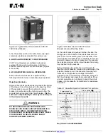
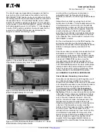
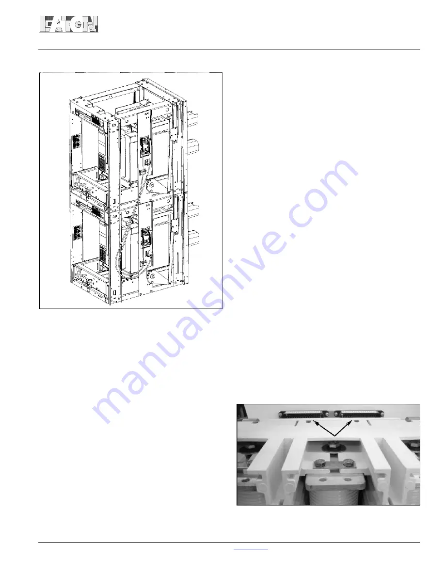
Figure 5-9 Typical Mechanical Cable Interlock
5-4 CONNECTION DIAGRAMS
Connection Diagrams for all circuit breakers are shown
in Figure
5-10, 5-11, 5-12
and
5-13.
5-4.1 TIMING
The opening and closing times for the circuit breakers
vary depending upon the control voltage and the power
rating. Typical values for VCP-T and VCP-TR breakers
are given below:
Closing Time
(from initiation of close signal to contact
make) - 45 milliseconds
Opening Time
(from initiation of trip signal to contact
break) - 17 to 29 milliseconds
Reclosing Time
(from initiation of trip signal to contact
make) - 250 milliseconds
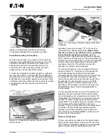
5-4.2 SECONDARY CONNECTIONS
Each secondary wiring point is identified and dedicated to
a specific function. The wiring points are finger safe
with no more than two wires per terminal. Two male type
secondary plug-in connectors are mounted on the top
rear portion of the circuit breaker. The plug-in
connectors are protected by a molded hood (Figures
5-
5, 5-6, 5-9
and
5-14).
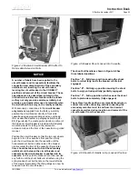
When the front cover of the circuit
breaker is removed, the top of each plug-in connector is
exposed. A label on each connector identifies the wiring
points (Figure
5-15).
There are two secondary connection options for fixed
type VCP-TR circuit breakers:
(1) Standard Secondary Disconnect Block - The
secondary disconnect block is a female connector with
male pins compatible with a male connector with female
pins mounted under the protective hood (Figure
5-16).
The customer plugs secondary wiring with crimp-on
connectors into the back of the female plug-in
connector.
(2)
Optional Screw Type Terminal Block - For those
customers preferring to wire to a terminal block, an
optional screw type terminal block is available for
terminating the secondary wiring leaving the female
secondary disconnect block. The terminal block is
available in kit form (Figure
5-17).
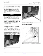
Drawout type VCP-T circuit breakers utilize an umbilical
cord utilizing a male connector with female pins on the
breaker end and a female connector with male pins on
the cassette end. One end plugs into its matching
connector mounted under a protective hood on the front
top portion of the circuit breaker. The other end plugs
into its matching connector mounted under the front top
portion of the drawout cassette.
A standard tool is available from the plug-in connector
manufacturer (AMP) to facilitate the removal of
secondary wiring from the plug-in connector (Figure
5-
18).
The connector halves must be separated to use this
tool.
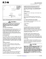
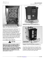
Figure 5-14 Secondary Connectors Shown Mounted
without Secondary Protective Hood In Place
Содержание 50 VCP-TR16
Страница 2: ......
Страница 19: ...Instruction Book Effective November 2017 Page 13 IB131016EN For more information visit www Eaton com...
Страница 69: ...Instruction Book Effective November 2017 Page 63 IB131016EN For more information visit www Eaton com...
Страница 71: ...Instruction Book Effective November 2017 Page 65 IB131016EN For more information visit www Eaton com...
Страница 76: ...Instruction Book Page 70 Effective November 2017 For more information visit www Eaton com IB131016EN...