background image

Maintenance   43 


8.  Re-tension  the  conveyor  belt  as  required.  Refer  to  the  instructions  for  Tracking 

the L-Sealer Conveyor Belt in the Adjustments section. 


Temperature Controller Replacement 


NOTE: 

Because  of  similar  physical  design  this  procedure  is 
applicable for temperature controllers for the L-sealer or the 
temperature controller for the shrink tunnel. 


NOTE: 

Shut off power to the machine before opening the panel door 
or accessing internal electronics and temperature controller. 


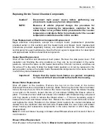
There are two options for removing the temperature controller. 


1. The  first  and  easiest  option  is  to  remove  and  replace  only  the  controller,  which 

reuses the receptacle sleeve and leaves all wiring intact. 


2. The second option is to disconnect  all wiring and replace the controller and sleeve 

together.  

 
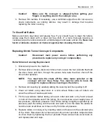
To reuse the housing and replace only the interior components of the controller, use a 
flat screwdriver to carefully press down on the tab, inside on top of the controller. (Take 
care  to  not  break  or  deform  the  tab  permanently.  See  the  following  illustration.) While 
the tab is depressed, pull on the front face of the controller to slide it out of the housing. 


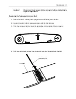
Connecting Pin 

Drive Belt 

Содержание Combination EC Series

Страница 1: ...EC Combination Series Semi Automatic L Sealer Tunnel User Guide EC2016T EC2016TK EC2028T EC2028TK ...

Страница 2: ......

Страница 3: ...ght and Trademarks Copyright 2017 Eastey Enterprises Inc All rights reserved All trademarks and brand names are the property of their respective owners Eastey Enterprises 7041 Boone Ave N Brooklyn Park MN 55428 Phone 763 428 4846 Fax 763 795 8867 1 800 835 9344 www eastey com EC2016T EC2016TK EC2028T EC2028TK ...

Страница 4: ......

Страница 5: ...stments 26 Shrink Tunnel Adjustments 33 Conveyor Belt Tension Adjustment 36 Maintenance 37 Preventative Maintenance 37 L Sealer Maintenance and Replacement 38 Shrink Tunnel Maintenance and Replacement 44 Troubleshooting 53 Parts List 62 Appendix A Electrical Schematics 71 Panel Layout 71 Electrical Schematic 73 Appendix B Temperature Setting Specifications for Shrink Wrap Plastics 75 Mushroom Inse...

Страница 6: ...hands head or any part of the body inside the confines of the machine unless the mechanism is securely fastened and the electrical supply is shut off Do not tamper with electrical wiring Use only the specified power supply cable Use only licensed electricians to check or repair electrical wiring Do not by pass any factory designed safety features such as guards interlocks switches etc In order to ...

Страница 7: ...modification Do not operate a machine if any modification has been made This equipment is designed for indoor operation in a typical clean dry factory environment Do not operate the machine in any extremely wet or oily environment that may exceed operating specifications Outdoor use is not recommended The use of certain types of plastic films in sealing and or shrink wrapping equipment may result ...

Страница 8: ...en wires or electrical components Only a trained electrician can uncover the electrical panel or box Burn hazard Indicates a hot surface Do not place your hand on or touch the hot surface as doing so could result in burns Shut down the machine and allow the surface to cool before touching surface Pinch hazard Do not place your hands or any object on the moving mechanism Shut down the machine befor...

Страница 9: ...y Frame Electrical Disconnect L Sealer Controls Casters Takeaway Conveyor with Height Adjustment Electro Magnets Film Roll Support Rollers Pin Perforator Film Roll Shrink Tunnel Exit End Shrink Tunnel Control Panel Shrink Tunnel Entrance Built In Drawer Leveling Legs Tunnel Conveyor Height Adjustment Wheel Height Adjust ...

Страница 10: ...maining two digits indicate length of front bar or nominal maximum length of front seal in inches either 16 or 28 inches T Takeaway conveyor The L Sealer is equipped with a takeaway conveyor that conveys the sealed package to be transferred onto the conveyor of the Shrink Tunnel K Knife Indicates hot knife seal bar The hot knife seal bar is an option and the unit can be ordered with hot knife or h...

Страница 11: ...ize of 20 in Maximum film width up to 24 inches Maximum film roll O D up to 12 inches 10 inches with power unwind Heavy duty casters for transportation within plant Leveling legs provide sturdy base once in place Custom two part epoxy finish resists scratching Side seal size of 16 in 20 in or 28 in 20 in 480V 50A Single Phase standard power requirement Easy to use design requires minimal training ...

Страница 12: ... cm 36 in 91 cm 1700 lbs 771 kg 1875 lbs 851 kg EC2028T 48 5 in 123 cm 65 in 165 cm 132 in 335 3 cm 28 in 71 cm 20 in 51 cm 16 in 41 cm 10 in 25 cm 36 in 91 cm 1550 lbs 703 kg 1700 lbs 771 kg EC2028T PFU 57 in 145 cm 65 in 165 cm 114 5 in 289 6 cm 28 in 71 cm 20 in 51 cm 16 in 41 cm 10 in 25 cm 36 in 91 cm 1800 lbs 817 kg 1975 lbs 896 kg EC2016T Manual Feed without PFU and without Inverter See Mac...

Страница 13: ... Seal Length S See Chamber Dimensions in the table at the top of the previous page for Heat Chamber Height H Width W and Height H 0 10 20 30 40 50 60 70 80 90 100 0 10 20 30 40 50 60 70 80 90 100 AIRFLOW ADJUSTMENT Heat Chamber Effective Height H Heat Chamber Tunnel Length D Heat Chamber Width W CAUTION PRECAUCION 2 75 To Floor 4 000 Conveyor Height 2 Max Adjustment Width A Height B Length C 0 10 ...

Страница 14: ...rtain any claim for loss or damage The agent will make an inspection and grant a concealed damage notation If you give the transportation company a clear receipt for the goods that have been damaged or lost in transit you do so at your own risk and expense All claims must be filled within five 5 months of the delivery date or the carrier will not accept them We are willing to assist you in every r...

Страница 15: ...g the location take into consideration the following factors 1 Adequate power supply nearby 2 Where is the machine in relation to the power source 3 Where is the machine in relation to any conveyor s necessary to move the wrapped product Alignment with packaging line 4 Convenience for the operator If there is any doubt get qualified assistance with your initial installation Location Requirements W...

Страница 16: ...to its location CAUTION If the combo unit must be lifted for moving use proper equipment when lifting and moving it to ensure it is secure and will not shift When the combo unit has been moved to its location use the levers on the casters to lock the wheels to prevent rolling and keep the unit in place A power cord with optional electrical plug should be installed by a licensed electrician CAUTION...

Страница 17: ...SV TZ4ST TEMP ER ATURE CONT ROLLER PV SV2 A T OUT EV1 EV2 SV TZ4ST TEMP ER ATURE CONT ROLLER 0 1 2 3 4 5 POWER OU T MODE AT11DN RUN A 0 1 2 3 4 5 POWER OU T MODE AT11DN RUN A DWEL L CONVEYOR FRONT TEM P CONTRO L SIDE TEM P CONTRO L POWER sec sec 0 10 20 30 40 50 60 70 80 90 100 PV SV TZ4L TEMP ER ATURE CONT ROLLER SV2 A T OUT EV1 EV2 P O WER ON ENCHUFE EN OFF A P ARADO HE ATER BANK BANCO de C ALEN...

Страница 18: ...e switch to toggle L Sealer power on or off 2 Dwell Timer setting for seal Duration of activation of seal arm electromagnets 3 Conveyor Timer setting for conveyor Length of time the conveyor will run for each item 4 Front Temperature Control Setting for temperature of front seal 5 Side Temperature Control Setting for temperature of side seal CAUTION When the power is turned on be aware of sealer h...

Страница 19: ...e heater bank on or off 4 Blower Speed Control Speed setting dial control for blower speed NOTE The blower motor speed setting dial control is located off the panel door to the left of the rest of the controls above the shrink tunnel entrance 5 Temperature Controller Temperature setting and current temperature inside the chamber is displayed CAUTION When the power is turned on be aware of heat ins...

Страница 20: ...d when changing the machine for a different size package or different size film It is adjusted by the adjustment knob at the bottom of the film rack The pin perforator is mounted inside the film rack of the machine to avoid dropping or damaging and so it is mounted out of the way Film Brake The film brake is positioned at the front end of the cradle rollers and creates a drag that maintains tensio...

Страница 21: ...uct on the product tray between the top and bottom layers of film to prepare to move the product and film into the sealing area Do not place product in the first few bags formed by the sealer they will not have any perforation holes in them because the sealer and pin perforator work together Perforation is required to allow air to vacate when the product passes through the shrink tunnel Cradle Mou...

Страница 22: ...should be directed three inches 3 above the loading tray coming off the power film unwind 2 Invert film around the inverting head Standing in front facing the machine move the loading tray out of the way Pull film toward you feeding it off the unwinder with the folded edge on the right Put the bottom layer of film under lower inverting plate Put top layer of film on top of upper inverting plate Wi...

Страница 23: ...n 2 Turn the Power toggle switch for the L Sealer to the On position to provide power to the L Sealer section of the combo unit 3 Turn on power to the shrink tunnel section of the combo unit by toggling the Power switch near the upper left of the shrink tunnel control panel to the On position Temperatures of the seals and temperature inside the tunnel will be displayed on the corresponding tempera...

Страница 24: ...ber 6 Place the product on the product tray The product tray separates the film allowing you to place the product between the upper and lower layers of film 7 Move the product into the seal head area pushing it to the left 8 Move hands out of the seal head area and pull the seal head down Let go of the handle as soon as the magnets activate The magnets hold the seal head down for the amount of tim...

Страница 25: ... production cycle perform an orderly shut down of the system First turn off the shrink tunnel Heater Bank toggle switch then turn off the L sealer Power toggle switch Wait for the shrink tunnel to cool to required cool down temperature before turning off the shrink tunnel toggle Power switch and if required shut off power at the main power lever only after the shrink tunnel has reached cool down t...

Страница 26: ... seal bar up slightly counter clockwise as viewed from above Adjustment has been set correctly when the magnets are energizing just as the seal bar comes into contact with the lower magnet pads Electromagnet Position Adjustment All magnets have been factory adjusted for equal sealing pressure throughout the length of both the front and the side seal bars If an adjustment is required however use th...

Страница 27: ...the 5 16 inch set screws 6 Cycle the seal head up and down Adjust set screws on head return cylinders for proper head speed and cushion L Sealer Timers and Temperature Controls Check dwell and conveyor run timing and temperature of front and side seals after making adjustments or after performing maintenance such as replacing seal pads cutting rules or hot knife inserts Adjust as required using th...

Страница 28: ...he idler roller The drive roller is the larger roller The idler is smaller and has a crown rounded surface that is higher at the middle and tapers outward to give the idler a slight barrel shape 2 Place the belt on the rollers in the center and tighten each adjustment screw as evenly as possible 3 Adjust the speed potentiometer on the conveyor timer adjustment screw for speed pot is at lower left ...

Страница 29: ...on identically and similarly but slightly differently from the shrink tunnel temperature controller Buttons required for programming and adjusting the temperature controller are protected from being pressed accidentally by a small horizontal cover below the display These buttons are accessed by opening the door by flipping it downward Information displayed by the temperature controller and the pro...

Страница 30: ...tion 6 MD key the mode key to change items to be set such as set value etc 7 EV2 Event 2 output signal lamp 8 EV1 Event 1 output signal lamp 9 OUT Output signal lamp 10 AT Signal lamp flashes while unit is auto tuning 11 SV2 Signal lamp for SV2 set value PV SV2 AT OUT EV1 EV2 SV MD AT SV 2 Point Setting C EV 1 Setting C EV 2 Setting C Loop Break Alarm sec P Band D Band sec Control Period sec Input...

Страница 31: ...the new value entered is applied To Change the Set Value for Over Temperature L Sealer Over temperature is factory set to 500 F but can be adjusted if required for your sealing application PV the Process Value is the actual temperature reading at the sealing elements PV and SV are mentioned in this procedure but they are only displayed at the beginning of the procedure 1 Press and hold the MD butt...

Страница 32: ...utton until LOC appears indicating that the Off setting is locked 3 Press the MD button until EU 1 appears Event 1 Below EU 1 AL 6 should appear If not use the up and down buttons to select AL 6 4 Now return to LOC and change it to On 5 Press and hold both the MD and up arrow buttons at the same time for three 3 seconds to access the other menu 6 Scroll through the menu using just the MD button an...

Страница 33: ... toggle switch for tunnel power controls the tunnel conveyor speed Operation is straightforward turning the dial counter clockwise to larger numbers increases motor speed and turning the dial clockwise to smaller numbers decreases motor speed Numbers on the dials from 0 to 100 represent percentage of the available speed range from 0 indicating minimal or no movement to 100 representing the fastest...

Страница 34: ...ntrol dial 1 PV Processing value red in color 2 SV Setting value green in color 3 Back forward down and up keys 4 Programming key access door Open to access programming keys 5 AT key the mode key to execute Auto Tuning function 6 MD key the mode key to change items to be set such as set value etc 7 EV2 Event 2 output signal lamp 8 EV1 Event 1 output signal lamp 9 OUT Main output light to indicate ...

Страница 35: ...ed the set point is factory set to 400 If you change this value you must make the following adjustment to ensure that your equipment will automatically shut down at 150 PV the Process Value is the actual temperature in the machine PV and SV are mentioned in this procedure but they are only displayed at the beginning of the procedure 1 Press and hold the MD button until SV 1 is displayed 2 Press th...

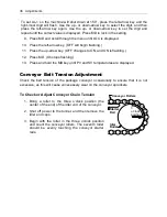
Страница 36: ... MD On stops flashing 13 Press and hold the MD key until PV and SV temperatures are displayed Conveyor Belt Tension Adjustment Check the belt tension of the package conveyor occasionally to ensure that it is not excessive as this will cause unnecessary wear on the conveyor sprockets To Check or Adjust Conveyor Chain Tension 1 Bring a roller to the three o clock position the center of the end of th...

Страница 37: ...ry Inspect the rollers of the conveyors regularly to ensure that no scrap pieces of film are wrapped around the rollers to cause sticking packages Instructions for cleaning rollers are provided later in this section Lubricate roller chains every 60 hours with a high temperature oil Use a brush to apply lubricant while running the conveyor slowly Inspect film cradle rollers Repair or replace as nee...

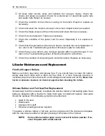
Страница 38: ...e condition of all warning and instruction labels Replace as necessary L Sealer Maintenance and Replacement Film Roll Support Rollers Make sure rollers stay clean and grease free If you should have to clean the rollers simply wipe them down with a clean lint free cloth If a more thorough cleaning is necessary wipe the rollers down with a mild detergent and water and let dry Never use harsh or abra...

Страница 39: ...he film clamp on the product tray 3 Remove the 8 32 flat head screw on both side seal and front seal bars 4 Remove the insert and cutting rule both at the same time 5 Place the replacement cutting rules into the new inserts both at the same time ensuring that the beveled edge is in the corner 6 Push the beveled edges together NOTE The inside beveled edges of the cutting rule need to come together ...

Страница 40: ...to the conveyor motor Red and yellow are together and capped Brown purple and orange are together and capped Black is connected to black for power White is connected to white for power Green is connected to green to ground or motor ground 3 Loosen the 20 drive roller adjustment bolts and remove the timing belt Remove the timing pulley from the motor requires an Allen or hex wrench 4 Remove the thr...

Страница 41: ...veyor Belt 1 Disconnect the L sealer power plug from the electrical power source 2 Loosen the idler roller to release tension until the belt is loose 3 Turn the conveyor belt to move the belt splice to the center of the conveyor 4 With the belt loose remove the connecting pin that holds the belt together Connecting Pin Drive Belt ...

Страница 42: ...nstall the new belt or reinstall the belt if still usable If the conveyor support plate requires replacement replace it before installing or reinstalling the belt 6 Install the replacement belt around the drive and idler pulleys 7 While the belt is still loose start connecting the ends by lining up the edges of the belt From the side of the belt replace the connecting pin ...

Страница 43: ...r There are two options for removing the temperature controller 1 The first and easiest option is to remove and replace only the controller which reuses the receptacle sleeve and leaves all wiring intact 2 The second option is to disconnect all wiring and replace the controller and sleeve together To reuse the housing and replace only the interior components of the controller use a flat screwdrive...

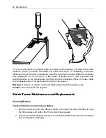
Страница 44: ...ure controller and thermocouple Refer to notes made during disassembly or the electrical schematic if necessary Warning If there is no control over heat interchange the thermocouple wires Caution Do not exceed 500 degrees Shrink Tunnel Maintenance and Replacement Cleaning Rollers To Clean Shrink Tunnel Conveyor Rollers 1 Run the conveyor until the affected rollers are inside the heat chamber to he...

Страница 45: ... that hold the drive motor and then through the access hole take the drive chain off the drive motor sprocket NOTE You must take the chain off the drive motor sprocket or the conveyor will not move freely You must be able to move the conveyor to replace silicone covering on the rollers 3 Remove old covering by carefully slitting the covering and then pulling it off 4 Clean all rollers using steel ...

Страница 46: ...de the shaft left or right The shaft sprockets must be adjusted for position All sprockets are fastened to the shaft by set screws Identify and replace any damaged or worn parts and reassemble in reverse order of disassembly Conveyor Motor Replacement Shut off the machine and disconnect main power Remove the drive end cap disconnect two 2 electrical wires from the drive motor and disconnect the mo...

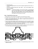
Страница 47: ...onveyor 2 Confirm that the edge loops curve back away from the direction of belt travel as shown in the following illustration If not check to make sure that the belt is not positioned backwards on the conveyor 3 Lay the strand down between the two belt ends and check to see that the edge loops are going in the same direction as the belt edge loops The strand must also be right side up for it to l...

Страница 48: ...he wire in the center space Once the center is connected you may remove the ties holding the belt ends together Step 2 Weave the Strand to One Side 1 Bend one end of the wire up and insert it around the z bend in the next space on the edge of the wire closest to you Space 5 in the following illustration Always try to avoid bending the wire in the z bend Far Edge Near Edge A C E B D 1 3 5 2 4 A E B...

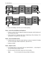
Страница 49: ... the side edge of the belt 5 Using the pliers connect the strand s edge loop to the belt s edge loop on the far edge 6 Connect the edge loop on the near edge of the belt to the strand s edge loop 7 Straighten the strand with the pliers Step 3 Weave the Strand to the Other Side 1 Repeat the steps in Step 2 going in the opposite direction weaving to the other side edge of the belt as shown in the fo...

Страница 50: ...s are not keyed to the drive shaft Step 5 Check Entire Belt Circuit Z bends should not come into contact with any conveyor component including end rolls wear strips transfer support rails nose bars etc Adjust as needed Step 6 Adjust Tension The wire belt used is a low tension belt Use minimal tension only enough so the sprockets properly engage the belt Run the conveyor and check to make sure it r...

Страница 51: ...off to the side Noting the heater bank position so it can be replaced in the same position remove the heater bank Reassemble components in the same manner in which they were disassembled Important Ensure that the heater bank frames are pushed completely in The end of the frame should be flush with the housing Blower Motor Replacement Shut off power to the machine Remove the top lid on the hood of ...

Страница 52: ... the same manner in which they were disassembled Chamber Cooling Fan Motor Replacement Shut off power to the machine Remove the top lid of the hood Disconnect the wires Remove four 4 20 screws which hold the cooling fan motor in place Take the motor out of the machine replace with the new motor and reassemble with four 4 20 screws removed earlier Reconnect wires to new cooling fan motor ...

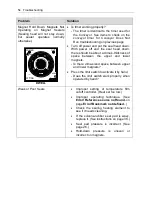
Страница 53: ...R sec With the seal head up the light in the left hand corner of the temperature timer stays lit all the time If the light is on bring the seal head down The light should start flashing Is the timer in A mode Mode selector is to the lower right corner of the dial Inside the conveyor speed dial is the setting between 0 and 5 Timer speed pot adjustment is to the lower left corner of the dial At the ...

Страница 54: ...n there should be about a dime s thickness of space between the upper and lower magnets Is there dime sized space between upper and lower magnets Press the limit switch to activate it by hand Does the limit switch work properly when operated by hand Weak or Poor Seals Improper setting of temperature film cutoff controller Heat set too low Improper operating technique See Error Reference source not...

Страница 55: ...econds Turning the selector at the lower right you see the modes change Keep turning until you return to mode A which is the factory setting Turning these two pots cleans the wipers inside the timer When bringing the seal down a light on the top left should come on and the light on the top right should flash If this is not happening switch the conveyor timer and the dwell timer If the magnets star...

Страница 56: ...ormation refer to the KBMM Installation and Operation Manual provided by the D C board manufacturer L1 P1 L2 P2 A1 A2 P3 F F AC Line 50 60 Hz Armature Motor Field Potentiometer Motor Armature Main Speed Potentiometer AC Line Input Front View Enable Switch Open to Stop Close to Run AC Line Fuse Supplied Separately Supplied Separately Armature Fuse is in center position Make sure jumper J2 Wiper Low...

Страница 57: ...tor went out There will be a point number for example 1 or 25 you will need this number when ordering a replacement resistor The motor is pulling more amps than the board is allowing Try adjusting the CL potentiometer on the motor controller board Bad idler or drive bearing If the red light is on disconnect the drive motor from the drive chain Power up the machine and operate the motor without any...

Страница 58: ...or load as speed is decreased Note Some fan cooled motors can be used over a wider speed range Consult the motor manufacturer for details WARNING Some motors have low speed characteristics which cause overheating and winding failure under light load or no load conditions If the motor is operated in this manner for an extended period of time it is recommended that the unloaded motor current be chec...

Страница 59: ...nstalled 4 All LED flash rates after recovered faults are 1 sec On Off 5 Drive will require manual restart to return the Status LED color to its normal flashing green state Problem Solution No air flow Continued 6 If one motor is running and one is not replace the faulty motor 7 If all motors are not running check for approx 220 VAC output voltage If there is no voltage and the green lights are on...

Страница 60: ... not pulling in replace contactor 5 If there is no 220 VAC check heater bank on off switch The best way to check this is to disconnect the wires and check resistances Ohms Delay cool down does not work Adjust temperature controller TT1 using the menus Menu 1 and Menu 2 that follow Refer to adjustment procedure to adjust the Delay Cool Down setting Temperature Controller Default Settings Menu 1 Tem...

Страница 61: ... AL1 250 AL2 450 AHYS 10 P 9 5 I 48 D 12 T 50 IN B 4 REST 2 0 LOC ON Temperature Controller 2 Su 2 32 same as 1 AL1 N A AL 2 450 same as 1 AHYS 2 P 9 5 same as 1 I 48 same as 1 D 12 same as 1 T 50 same as 1 IN B 4 same as 1 REST 2 0 same as 1 LOC ON same as 1 ...

Страница 62: ...1 CR3 EAST0031 Main Contactor 1 TMR 1 EAST1030 Timer Dwell 1 TMR 2 EAST1030 Timer Conveyor 1 LS 2 EAST0029 Magnet Limit Switch 1 LS 3 EAST0029 Conveyor Limit Switch 1 M1 EAST0063 Conveyor Motor 1 T 3 EAST0036 Magnet Transformer 1 EAST0038 AC To DC Bridge Rectifier 1 Mag 1 2 ECOS0057 Electric Magnetic Hold Down 2 EAST0663 Increased Pressure Magnet Transformer EAST0031 1 40 Amp 2 pole 220 V GE conta...

Страница 63: ...3 Conveyor Motor 20 28 EAST0038 Bridge Rectifier EAST0078 Capacitor Mallory EAST0421 1 Contactor 2 Pole 25 Amp 220 Volt GE EAST0421 Contactor 2 Pole 25 Amp 220 Volt S S ET000134 Disconnect Box 60 Amp 2 Pole Combo Unit ECOS515 Fuse 0 5 Amp Ceramic Slo Blo for Conveyor EAST0210 Fuse 1 Amp 250 Volt ET000301 Fuse 10 Amp 250 Volt EAST0674 Firerod Cartridge Heater 16 110 V EAST0675 Firerod Cartridge Hea...

Страница 64: ...07 Arm Casting Outfeed 20 EAST0061 Barrel Nut Conveyor EAST0052 Bearing Conveyor Guide Idler Roller EAST0378 Bearing Film Rack Roller Large EAST0380 Bearing Film Rack Roller Small EAST0254 Bearing Steel Drive Roller 1616Z KYK XH360 Bolt 1 Shoulder EAST0462 Bolt Film Rack Guide EAST0379 Bolt Film Rack Roller Large EAST0381 Bolt Film Rack Roller Small ...

Страница 65: ... Black EAST0058W Conveyor Belt EM2028 EC2028 White SUB00079 Conveyor Crank Handle Assembly SUB00165 Conveyor Guide Roller 20 Side Seal complete EAST0465 Counterweight 30 40 EAST0526 Counterweight EAST0640 Crank Handle Conveyor threaded EAST0513 Crossover Bar 16 EM2016 EC2016 EAST0550 Crossover Bar 28 EM2028 EC2028 EAST0816 Cutting Rule 16 inch Front Supra Silverstone EAST0817 Cutting Rule 28 inch ...

Страница 66: ...erstone EAST0549 Duo Seal Poly Insert 28 inch Front Bar Supra Silverstone EAST0516 Duo Seal Poly Insert 20 inch Side Bar Supra Silverstone EAST0509 Felt Pad SUB00123 Film Rack Guide Assembly EAST0674 Firerod Cartridge Heater 16 inch 110 Volt EAST0497 Firerod Cartridge Heater 16 inch 220 Volt EAST0675 Firerod Cartridge Heater 28 inch 110 Volt EAST0555 Firerod Cartridge Heater 28 inch 220 Volt EAST0...

Страница 67: ...r EINVT124 Inverting Rod 24 Upper or Lower EAST0441 Knob Film Rack Guide ETC00210 Knob Pin Perforator ETC00002 Knob S Handle Conveyor EAST0900 Magnet Holder Upper Center Block EAST0901 Magnet Holder Upper Pad Block EAST0741 Magnet Holder Lower EAST0338 Magnet Holder Upper SUB00065 Magnet Upper EAST0029 Micro Limit Switch Safety Override Pulse Conveyor ETC00310 Micro Switch On Off Face Plate EAST01...

Страница 68: ...l EM2016 EC2016 Left SEAST0142R Product Separator Tray Stainless Steel EM2016 EC2016 Right Product Separator Tray Stainless Steel EM2028 EC2028 Left EAST0317R Product Separator Tray Stainless Steel EM2028 EC2028 Right ESC00542 Relay Base for 220 Volt SignaLine Timer EAST0495 Relay Solid State EAST0079 Resistor Hole Punch EAST0053 Roller With Sprocket 20 inch Conveyor Drive SUB00126 Roller 26 Film ...

Страница 69: ...er EAST0310 Separator Rod Power Film Unwind EAST0047 Shaft 21 inch Rear Head Return For L Sealer EM2016 EC2016 EAST0048 Shaft 33 inch Rear Head Return For L Sealer EM2028 EC2028 EAST0369 Shaft Pin Perforator EAST0515 Spacer Block Corner EAST0315 Speed Control Without Dial Kit DC Control EAST0315A Speed Control Dial Kit EAST0209 Sponge Rubber 20 Ft Roll EAST1007 Spring Safety Shield Return EAST0199...

Страница 70: ...ng Belt Drive L Sealer EC2016 EM2016 EAST0055 Timing Belt Drive L Sealer EC2028 EM2028 EAST1000 Timing Belt Power Film Unwind Old Style EAST0050 Transformer Stepdown 220 Volts to 110 Volts For Hole Punch EAST0036 Transformer Stepdown 220 Volts to 30 Volts SUB00488 Transition Chute Transfer Between Sealer and Tunnel SUB00300 Transition Roller Between Sealer and Tunnel Combo SUB00301 Transition Roll...

Страница 71: ...ealer LS1 SSR1 SSR2 LS3 Pulse L S Power On Off Dwell Timer Relay Solid State Relays Timer Conveyor TT1 Temperature Control Front TT2 Temperature Control Side Main Fuse Block Main Fuse Block Conv L S Magnet Transformer Terminal Strip Bridge Rectifier wire way wire way wire way wire way ...

Страница 72: ...72 Appendix A Electrical Schematic Panel Layout Shrink Tunnel F3 ON OFF ON OFF F4 CR2 CR1 F5 F1 L1 F2 L2 F3 L3 F6 F7 F8 POWER HEATER BANK CONVEYOR SPEED CONTROL DC CONTROL TT1 G BLOWER SPEED CONTROL ...

Страница 73: ...Appendix A Electrical Schematic 73 Electrical Schematic L Sealer ...

Страница 74: ...74 Appendix A Electrical Schematic Electrical Schematic Shrink Tunnel Variable Speed 220V 40 50A 480V 20 25A Single Phase ...

Страница 75: ...C Poly Vinyl Chloride Temperature settings Pad type Dwell Time 325 F front bar 325 F side bar Felt Approximately 1 second Polyolefin Temperature settings Pad type Dwell Time 335 F front bar 335 F side bar Sponge rubber Approximately 1 second Polyethylene Temperature settings Pad type Dwell Time 360 F front bar 360 F side bar Sponge rubber Approximately 1 5 second ...

Страница 76: ...stimating Table To calculate estimated per package cost for manual and semi automatic L sealers use the following formulas 1 Center Folded film width of roll of film 2 Cutoff Film length film going across front seal bar 3 Film usage to calculate the amount of film used per package 4 Per package cost ...

Страница 77: ... Size Estimation The following Eastey Enterprises side seal bar size dimensions are provided to make sure your product will fit under the side seal bar You will need to know your product height and width to use these figures effectively Hot Knife Hot Wire ...

Страница 78: ... defects in material and workmanship Sealing Quality Sealing quality achieved in a given application is dependent on the installation the material handling and the maintenance provided Eastey makes no warranty that the sealing quality achieved in an application will be the same as that achieved on a test piece in our demo facility Shipping Policy Customer pays all incoming shipping If the item is ...

Страница 79: ... buyer Limited Warranty THE ABOVE WARRANTY IS EXCLUSIVE AND IN LIEU OF ALL OTHER WARRANTIES WHETHER EXPRESSED OR IMPLIED INCLUDING THE IMPLIED WARRANTIES OF MERCHANTABILITY FITNESS FOR A PARTICULAR PURPOSE AND NONINFRINGEMENT Disclaimer of Damages REGARDLESS OF WHETHER ANY REMEDY SET FORTH HEREIN FAILS OF ITS ESSENTIAL PURPOSE IN NO EVENT WILL EASTEY ENTERPRISES INC BE LIABLE FOR ANY SPECIAL CONSE...

Страница 80: ...rmance Series L Sealer please contact Eastey Technical Service at one of the numbers listed below Toll Free Phone 800 835 9344 Phone 763 428 4846 Fax 763 795 8867 E mail info eastey com Web www eastey com Thank you again for your purchase of Eastey products We are pleased to be a part of your packaging needs ...

Страница 81: ......

Отзывы: