background image

20

E-flite Piper Pawnee ARF Assembly Manual


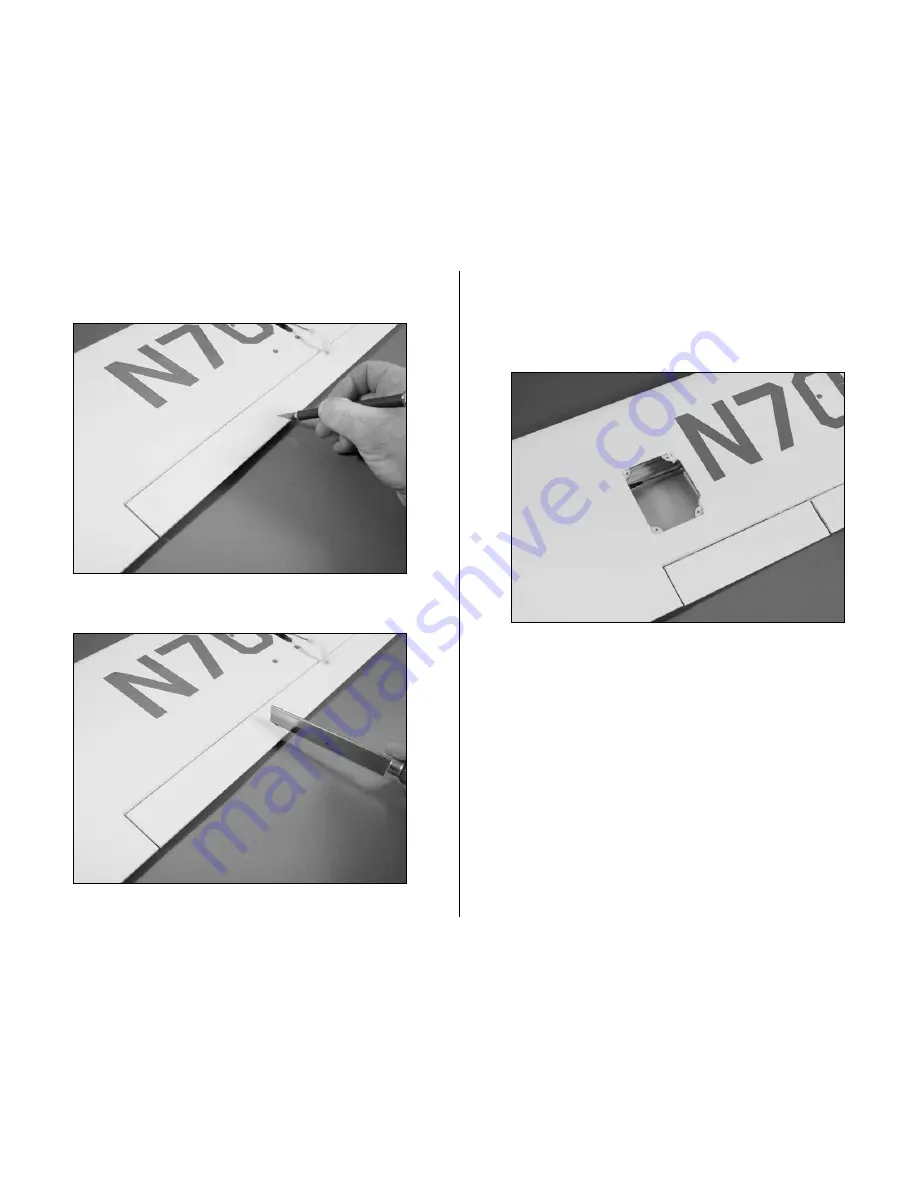
2. Use a hobby knife to cut the covering separating the 

flap and aileron


3. Use a razor saw to separate the flap from the aileron.


4. Use a hobby knife to remove the covering for the  

flap servo. Use a covering iron to iron the edges of  

the covering into the opening to have a visually 

appealing flap servo installation. Save the covering  

for the following step.

Содержание EFL2650

Страница 1: ...Specifications Wingspan 62 in 1575mm Length 41 5 in 1050mm Wing Area 550 sq in 35 5 sq dm Weight w Battery 4 4 25 lb 1800 1900 g Weight w o Battery 3 25 lb 1450 g Piper Pawnee 15e ARF Assembly Manual...

Страница 2: ...d into sections to help make assembly easier to understand and to provide breaks between each major section In addition check boxes have been placed next to each step to keep track of each step comple...

Страница 3: ...u are using an existing transmitter just purchase the other required equipment separately We recommend the crystal free interference free Spektrum DX6i 2 4GHz DSM2 6 channel full range transmitter and...

Страница 4: ...Device Battery Connector Male Female included with our ESC EFLC3005 Celectra 1 to 3 Cell Li Po Charger Optional Accessories EFLA110 Power Meter Required Tools and Adhesives Tools Equipment EFLA250 Par...

Страница 5: ...rranty is limited to the original Purchaser Purchaser and is not transferable REPAIR OR REPLACEMENT AS PROVIDED UNDER THIS WARRANTY IS THE EXCLUSIVE REMEDY OF THE PURCHASER This warranty covers only t...

Страница 6: ...Your local hobby store and or place of purchase cannot provide warranty support or repair Once assembly setup or use of the Product has been started you must contact Horizon directly This will enable...

Страница 7: ...following address Horizon Product Support 4105 Fieldstone Road Champaign Illinois 61822 Please call 877 504 0233 with any questions or concerns regarding this product or warranty Safety Precautions a...

Страница 8: ...and Adhesives 1 Phillips screwdriver Hex wrench 1 5mm Threadlock File Medium CA Adjustable wrench 2 Note We will assemble the landing gear and set them aside until needed This will reduce the number o...

Страница 9: ...the rear hub and which is the front hub m 4 Slide the rear hub onto the axle With the 5 32 inch wheel collar in the center of the axle tighten the setscrew using a 1 5mm hex wrench to secure the colla...

Страница 10: ...he holes when inserting the front hub in the wheel m 6 Use four 2mm x 15mm sheet metal screws and a 1 Phillips screwdriver to secure the front and rear hubs You can now install the hubcap onteh wheel...

Страница 11: ...ide the tail wheel onto the tail gear wire Use a 5 64 inch wheel collar and setscrew to secure the tail wheel Remember to use threadlock on the setscrew to prevent it from vibrating loose 10 Use mediu...

Страница 12: ...ips screwdriver 1 Felt tipped pen String Side cutters Pin drill Pliers Drill Thin CA Drill bit 1 16 inch 1 5mm 5 64 inch 2mm 1 Plug the aileron servos into the radio system and make sure they operate...

Страница 13: ...the servo mounting block Use a pencil to mark the locations for the servo mounting screws on the blocks The servo should not touch the cover to prevent it from absorbing vibrations from the airframe m...

Страница 14: ...ng blocks m 9 Secure a 6 inch 152mm servo extension to the servo lead using string or a commercially available connector m 10 Tie a weight to a 24 inch 600mm piece of string and lower the string into...

Страница 15: ...ugh the wing and out of the hole Note Tape the extension to the wing so it does not fall back into the hole m 12 Secure the servo cover using four 2mm x 8mm sheet metal screws and a 1 Phillips screwdr...

Страница 16: ...in the horn align with the hinge line and b the pushrod is 90 degrees to the hinge line Use a felt tipped pen to transfer the locations for the two mounting screws onto the aileron m 16 Use a drill an...

Страница 17: ...Phillips screwdriver and the control horn backplate to secure the control horn to the aileron m 19 Center the aileron and aileron servo and use a felt tipped pen to mark where the pushrod crosses the...

Страница 18: ...hrough the hole in the servo arm m 23 Use a pushrod connector to secure the pushrod wire to the servo arm Use side cutters to remove any excess wire m 24 Use side cutters to trim all but 1 16 inch 1 5...

Страница 19: ...connector 2 Servo mounting block 5 8 x 3 8 x 3 8 inch 16 x 9 5 x 9 5mm 4 Required Tools and Adhesives Drill Thin CA Drill bit 1 16 inch 1 5mm 5 64 inch 2mm 6 minute epoxy Pencil Phillips screwdriver 1...

Страница 20: ...flap and aileron 3 Use a razor saw to separate the flap from the aileron 4 Use a hobby knife to remove the covering for the flap servo Use a covering iron to iron the edges of the covering into the op...

Страница 21: ...re with each other Use a covering iron and the material from the opening for the flap servo to beautify the ends of the flap and aileron 6 The installation of the flap servo and linkage follows the ex...

Страница 22: ...tack tape Pencil Felt tipped pen Sandpaper Rubbing alcohol Paper towels 1 Mix approximately 1 2 oz 15 ml of 30 minute epoxy Apply the epoxy to the mating sides of each of the joiners 2 Use clamps or t...

Страница 23: ...uld slide in up to or beyond the line drawn on it in the previous step If not lightly sand the end of the joiner until it does Important It is suggested to make a dry run of the following steps to mak...

Страница 24: ...he joiner into the wing panel and clean up any excess epoxy using a paper towel and rubbing alcohol Use enough epoxy that is flows out of the joiner pocket when the joiner is inserted Repeat Steps 6 t...

Страница 25: ...Ruler T pins Thin CA Rotary tool Drill bit 1 16 inch 1 5mm Square 30 minute epoxy Phillips screwdriver 2 Medium CA Paper towel Rubbing alcohol 1 Attach the wing using two 8 32 x 1 inch machine screws...

Страница 26: ...are parallel If not lightly sand the stab saddle until they are Align Wing and Stabilizer 6 Double check the adjustments from Steps 1 through 3 Use a felt tipped pen to trace the outline of the fusela...

Страница 27: ...op and bottom of the stabilizer Slide the stabilizer back into the fuselage and clean up any excess epoxy using a paper towel and rubbing alcohol 9 Use a rotary tool and a 1 16 inch 1 5mm drill bit to...

Страница 28: ...lizer and elevator 13 Align the elevator with the tip of the stabilizer so they do not bind during operation Apply a few drops onto each hinge Make sure to apply the CA on both the top and bottom of t...

Страница 29: ...o break in the hinges 16 Repeat Steps 10 through 15 to attach the remaining elevator to the stabilizer 17 Place the fin in position on the fuselage Trace the outline of the fuselage onto both sides of...

Страница 30: ...ok and loop material Required Tools and Adhesives Phillips screwdriver 1 Scissors Pliers Side cutters 6 minute epoxy Felt tipped pen Thin CA Hobby Knife Drill Drill bit 1 16 inch 1 5mm 5 64 inch 2mm 1...

Страница 31: ...s into the tubes inside the fuselage You will need to use a hobby knife to trim the covering near the tail so the pushrods can exit the fuselage 4 Position the rudder servo in the fuselage Mark the lo...

Страница 32: ...ill the four holes for the servo mounting screws 6 Apply a few drops of thin CA to each of the holes drilled in the previous step to harden the surrounding wood 7 Mount the servo using the screws prov...

Страница 33: ...essively outside the fuselage as this will greatly reduce the range of your radio system m 10 Place a clevis retainer onto a nylon clevis then thread the clevis onto the rudder pushrod m 11 Remove the...

Страница 34: ...ous step to harden the surrounding wood m 14 Mount the rudder control horn using a 1 phillips screwdriver and two 2mm x 15mm machine screws m 15 Use a felt tipped pen to mark the pushrod where it cros...

Страница 35: ...pushrod wire to the servo arm Use side cutters to remove any excess wire 18 Repeat Steps 10 through 17 to install the first elevator pushrod Before connecting the pushrod to the servo arm make sure t...

Страница 36: ...3mm x 8mm machine screws and a 2 Phillips screwdriver It will be necessary to trim and possibly bend the final elevator pushrod to prevent it from hitting the pushrod connector Once complete coat this...

Страница 37: ...ack tape Pin drill Ball driver 3 32 inch 1 Attach the X Mount to the motor using the screws provided with the motor and a 2 Phillips screwdriver Make sure to use threadlock on all four screws so they...

Страница 38: ...If not follow the directions included with your speed control to change the direction of the motor rotation Important Information About Your Brushless ESC Make sure your ESC brake is programmed to Of...

Страница 39: ...ng onto the shaft An unbalanced propeller may strip the gears or cause poor flight characteristics Note If it is necessary to enlarge the hole in the propeller make sure to check the balance of the pr...

Страница 40: ...he cowl lines up with the stripe on the fuselage before drilling 12 Use a pin drill and 1 8 inch 3mm drill bit to drill the four holes in the cowling for the mounting screws 13 Apply a few drops of th...

Страница 41: ...y glue Phillips screwdriver 1 2 Low tack masking tape Hex wrench 7 64 inch Threadlock Hobby knife Medium CA 1 16 inch 1 5mm drill bit or T pin 1 Use a hobby knife to remove the covering to expose the...

Страница 42: ...l bit or T pin through the hole in the strut mounting block from the inside of the fuselage to puncture the fuselage covering 5 Plug the Y harnesses for the flaps and ailerons into the receiver Connec...

Страница 43: ...levator with the radio system Moving the elevator stick down will make the airplane elevator move up 3 Check the movement of the ailerons with the radio system Moving the aileron stick right will make...

Страница 44: ...ol of all functions If not don t attempt to fly Have your radio equipment checked out by the manufacturer 2 Double check that all controls aileron elevator rudder and throttle move in the correct dire...

Страница 45: ...r the instructions Taxi into the wind and set the throttle trim so the motor idles with the prop spinning You will need about 200 feet to take off so ensure you have plenty of room We fly at the local...

Страница 46: ...n point for the recycling of waste electrical and electronic equipment The separate collection and recycling of your waste equipment at the time of disposal will help to conserve natural resources and...

Страница 47: ...established in front of which all flying takes place with the other side for spectators Only personnel involved with flying the aircraft are allowed at or in front of the flight line Intentional flyi...

Страница 48: ...11066 2007 Horizon Hobby Inc 4105 Fieldstone Road Champaign Illinois 61822 877 504 0233 horizonhobby com E fliteRC com...

Отзывы: