background image

D9

35

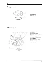
01 upper cover

02 recovery tank

01-01 upper cover
01-02 sealing strip

02-01recovery tank
02-02 shaft pin
02-03 filter cap + sponge
02-04 drain out plug fixed bracket
02-05 drain out plug
02-06 drain out hose fixed bracket
02-07 pipe clamp
02-09 suction motor assembly
02-10 level sensor
02-11 seat cushion

Содержание D9

Страница 1: ...D9 Floor Scrubber Manual Please read this manual carefully and make sure fully understand before using Please keep this Manual for future reference Dycon Cleantec Co Ltd ...

Страница 2: ...onfigure 7 Battery maintenance content 9 Brush loading and unloading 10 Driving skills instruction 16 Operation essentials 17 Main parts 18 Ater work and maintenance 21 Replacement procedure of rubber 22 Brush assembly and disassembly 23 Clean the recovery tank 24 Common problems and Troubleshooting 26 Battery 31 ...

Страница 3: ...perator must be trained in the master control of the machine forward backward turning obstacle avoidance and emergency stop after the operation then can operate independently when working please do not exceed 7 angle 4 degrees to operate the machine When the machine is backward the horn will automatically ring must be slow flammable substances may cause explosion or fire please do not use flammabl...

Страница 4: ...peed rpm 200 Brushmotor V Watt 24 2 500 Brushpressure Lb 99 Squeegee Inch 43 Solution Tank Gallon 39 63 Recovery Tank Gallon 47 55 Batteries V AH 4 6V 200 Type batteries standard GEL Sound Level dBA 68 Weight with batteries lb 838 Run time per charge Hour 3 4 Cleaning Productivity Ft Hour 55972 8 Machine sizes L W H Inch 64 57 35 43 56 30 Gradeability 20 ...

Страница 5: ...the suction system will automatically shut down the squeegee will be automatically recovered Drainage switch Direct control the machine drainage system The brush opens the drainage system opens automatically If you do not need to drain the water press the switch to turn off the system Brush indicator The light indicates that the brush system is in working condition Otherwise indicates cease Suctio...

Страница 6: ...y is regulated by the water regulating handle and the operator regulates the water quantity according to the work need warning For warning appear in the face of the text operators should not only seriously read but also keep in mind can not be violated once violated are likely to cause adverse consequences careful for carefull appear in the face of the text operators should pay attention to it in ...

Страница 7: ...den so as not to damage the people and the machine The machine will automatically turn off the brush tray when it is not in use to protect the ground from damage Please use dry powder fire extinguisher when the machine is on fire Please don t use water to extinguish the fire Keep away from dangerous shelves or scaffolding Select proper operating speed according to traction force Note in order to a...

Страница 8: ...rface Battery connection Battery plug 1 located in the battery above please connect with plug 2 Do not arbitrarily change the battery connector if unauthorized changes will lose the battery charger the quality assurance from the original factory battery charging connection Battery charging port located inside of a post operation As shown in figure 1 lease connect charging port 2 with figure 1 plea...

Страница 9: ...an1 2 Red light said power is close to depletion after a period of time the red light alarm The original configuration of the machine is a high performance deep circulation and maintenance free battery you must use the original configuration of the charger the charger has the function of intelligent management no need to worry about excessive charging In the use of the day allowed in the middle fo...

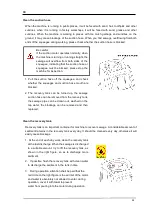
Страница 10: ...ecovery tank from the front part of the seat 2 the support rod will slide in the chute When the support rod falls into the positioning groove you can release your hand The support rod will keep the recovery tank in a fixed position 3 recovery tank is closed the support rod shall be removed from the positioning buckle to make the support rod return to the chute During the placing process the hand s...

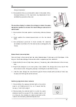
Страница 11: ...trument panel to ensure that the machine does not have anything to do by manually putting the brush into the machine Be careful rubber of squeegee in the transport process may appear deformation because of extrusion do not use any solvent or hot air blowing process LINATEX professional rubber has a strong recovery elasticity as long as lift the squeegee and keep it overnight it will be recovery Be...

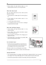
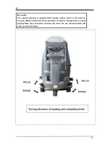
Страница 12: ...hold the brush with both hands and rotate the brush in the opposite direction Note during each operation make sure there is no impact on other surrounding objects or personnel Note when each operation make sure that no affection for circumambient object or personnel we recommend that you change the left brush and the right brush position weekly When you find that the bristles of the brush have wor...

Страница 13: ... may be blocked 2 check the discharge pipe cover of recovery tank is effectively closed or not 3 check the recovery tank cover ring is intact or not 4 Check the air inlet and filter sponge to make sure the filter sponge is in good condition Do not remove the water splash proof device no this device cleaning water will cause a large spill if work in oil area pay more attention to clean the splash b...

Страница 14: ...storage tank water status cleaning agent concentration should be adjusted according to the cleaning instructions The air inlet device is directly connected with the water suction motor and the water can not be poured in the cleaning and maintenance process If there is water entering it will cause damage to the motor In this case you will lose the quality guarantee please select the appropriate det...

Страница 15: ... ready state and the brush system will only enter the working state when the machine enters the forward state suction start B water suction indicator light is on press the suction button the suction system is in the working state squeegee fall down automatically and the water suction motor will automatically open if the surface dirt is particularly serious you can choose to brush function only ope...

Страница 16: ...0 The machine has a foot switch a key control design when you complete the work settings as long as the pedal down the machine will operate according to the set requirements when the machine starts to run the operator should check if the brush system is effectively lowered if the suction system normal if the water suction effect normal If inappropriate timely adjustment brush system and suction sy...

Страница 17: ...ater absorption system in the new area before operation to examine the working site running the line on the machine to advance planning should not blindly follow the act to ensure the safety of operators and equipment and the safety of surrounding objects Although the machine has a strong suction but after all is not sweeping machine in the operation it is best to pre cleaning the work site remove...

Страница 18: ...from slipping Of course it can also be used as an auxiliary brake in an emergency 5 In normal operation the machine does not need to use the brake device The machine has a complete automatic brake damping design As long as the electronic accelerator is released the machine will stop quickly without worrying about safety issues 6 This machine does not have a manual clutch switch which saves the tro...

Страница 19: ... stops running operator want to leave the machine please pedal brake on the parking space to ensure that the machine safe parking At run time in case of emergency can also use the left foot on the pedal brake The equipment has a recovery tank full water automatic warning and closed water suction system When the sewage in the recovery tank reaches the warning water level the system will automatical...

Страница 20: ... step down the operation control switch the machine can start operation When the sewage pipe is put into the pipe rack the pipe frame adhesive bar is pulled out first and then the pipe is pushed into the position with glue tape When an emergency occurs you can turn off the key switch step on the brake pedal or pull down the emergency shutdown switch to stop the machine running in the shortest poss...

Страница 21: ...eration on the one hand may affect the cleaning effect on the other hand may cause accidents The equipment has electronic damping brake device as long as the right foot to loosen the control switch the driving speed will be significantly damped until stop When the machine is not in use the brake pedal should be placed in the retaining position to prevent the machine from shifting The dotted area o...

Страница 22: ... solution tank should be emptied after every day work 3 rinse the squeegee clean the surface of the machine with dry cloth the parts of the electric appliance can not be rinsed directly with water 4 close brush suction operation switch 5 close water valve water quantity regulating switch on control panel 6 turn the key counter clockwise to the OFF position and pull the key out 7 depress the foot b...

Страница 23: ...egee system at will 3 Dismount the butterfly nut to remove the pressure plate of the rubber Before dismounting the pressure plate pay attention to the fixed position of the pressure plate and do not install it reversely 4 The rubber shall be kept in a natural and flat state before fixing Do not pull the rubber deliberately After fixing the whole rubber shall be in a flat state If there is any dist...

Страница 24: ...n depress the switch by right foot it will be ok if you feel the brush already been assemblied If you feel the brush is not assemblied repeat 3 operation Careful please take gloves and avoid hands hurt Warning The filter screen in the filter is an important part of the drainage system Without the filter screen the drainage system will be blocked The filter screen shall be inspected once a week by ...

Страница 25: ... is an important container for machine to recover sewage A considerable amount of sediment remains in the recovery tank every day It should be cleaned every day otherwise it will easily cause blockage 1 At the end of each day work clean the recovery tank at the last discharge When the sewage is discharged to a suitable amount try to lift the recovery tank as shown in the right figure so as to disc...

Страница 26: ...or cleaning and then installed after completion Be careful In order to facilitate the cleaning operation we designed the cover of the recovery tank to be removable When cleaning the recovery tank we can remove the cover of the recovery tank and reinstall it after cleaning When cleaning the recovery tank never pour water into the air inlet of the motor The air inlet is directly connected to the suc...

Страница 27: ...he water outlet is not normal please check whether there is foreign matter blocking in the solution tank filter screen must be installed If there is no filter screen the solenoid valve or other pipelines will be damaged Routine inspection can t be ruled out then we need to ask professional maintenance personnel When the machine pass through it will leave a silk like trace after squeegee There are ...

Страница 28: ...l of the squeegee the two pressure dividing wheels shall be lowered equally first make the pressure dividing wheel contact the ground second adjust the pressure dividing wheel to make the bending degree of the rubber basically consistent under the working condition If the squeegee can not be adjusted according to the above method maybe the squeegee bracket or squeegee suspension system has serious...

Страница 29: ...se a lot of problems In the long run it will cause damage to the suction motor so please pay more attentions 1 check whether the use of high foam cleanser if necessary add a little defoamer to the recovery tank 2 If high foam detergent is not used please check whether the dosage ratio is too much This phenomenon can be changed by properly controlling the concentration of use 3 under the same dosag...

Страница 30: ...rmation between brush and squeegee system 3 Check whether the microswitch at the charging port is displaced and stuck 4 Ask professionals to check whether the controller lifting push rod and other parts are in fault No or small water output 1 The filter of the drainage system is an important part to ensure that the solenoid valve and the drainage system are not blocked and it must be in good condi...

Страница 31: ... cleaning brush Polypropylene cleaning brush PPL It is suitable for various types of floor it is wear resistant and high temperature resistant hot water can not exceed 60 As PPL is not hygroscopic it can also maintain its characteristics when working on wet floor Nylon brush It is suitable for various types of floor it is wear resistant and high temperature resistant hot water can not exceed 60 Be...

Страница 32: ...eight of each battery is more than 40kg It should be placed carefully to avoid damage to the shell The battery pack of this machine is composed of four 6V batteries in series and the connection shall be completed by professionals to ensure correct and reliable connection The placement of four batteries should leave space for each other to help the machine cool down Battery maintenance Battery main...

Страница 33: ... time every day If the daily working time is long it is allowed to conduct supplementary charging in the middle but it is absolutely not allowed to replace the normal charging with supplementary charging Such operation will cause the battery performance to decline rapidly and the storage capacity to decline 4 Keep the battery at full power and do not leave the battery at power shortage 5 If it is ...

Страница 34: ...ine is equipped with Linatex rubber which is the same as Tennant Nilfist and Karcher brand machines It has the characteristics of good wiping effect wear resistance and long use time The use of brand rubber will make you feel its charm ...

Страница 35: ...ose 04 battery 05 solution tank 06 suction hose 07 squeegee assembly 08 squeegee connection assembly 09 squeegee lifting assembly 10 machine frame assembly 11 brush lifting assembly 12 brush assembly 13 brake system 14 clean water pipe system 15 machine body console 16 directional control system ...

Страница 36: ...r 01 02 sealing strip 02 01recovery tank 02 02 shaft pin 02 03 filter cap sponge 02 04 drain out plug fixed bracket 02 05 drain out plug 02 06 drain out hose fixed bracket 02 07 pipe clamp 02 09 suction motor assembly 02 10 level sensor 02 11 seat cushion ...

Страница 37: ...tor 02 09 03 suction motor seal ring 02 09 04 motor fixed column 02 09 05 shock reduction column 02 09 06 suction motor fixed plate 02 09 07 motor connection seat 02 09 08 vacuum tube cover 02 09 09 cover plate 02 09 10 muffler box 02 09 11 connection tube ...

Страница 38: ...e way 05 06 arm tie 05 07 fixed seat 05 08 hinge 2 05 09 solution tank cover 05 10 pipe joint 05 11 sealing 05 12 joint 07 01 front press plate 07 02 front rubber 07 03 squeegee 07 04 wheel 07 05 base 07 06 spring 07 07 wheel frame 07 09 nut 07 10 partial pressure wheel 07 11 screw 07 12 rear rubber 07 13 rear press plate ...

Страница 39: ...ting assembly 08 01 tail frame 08 02 spring 08 03 bracket 08 04 connection 1 08 05 spring 08 06 connection 2 08 07 spring 2 08 08 bracket 08 09 screw 09 01 squeegee push rod 90 02 rope 09 03 fixed pulley 1 movable pulley 09 04 bracket 09 05 fixed pulley 2 ...

Страница 40: ...t 2 10 02 machine frame assembly 10 03 bearing 10 05 chain wheel 10 09 front fork 10 11 front wheel 10 13 front wheel shaft 10 14 bracket 10 15 wheel 10 16 plate 10 17 rear drive assembly 10 18 rear wheel 2 10 19 nut 10 20 wheel cover 10 21 controller ...

Страница 41: ... 12 brush assembly 11 01 brush push rod 11 02 push arm 11 03 chain 11 04 adjusting rod 2 11 05 bracket 11 06 shaft sleeve 3 12 01 brush motor 2 12 02 wheel 2 12 03 brush cover assembly 12 04 apron 12 05 06 154 brush head 12 07 brush ...

Страница 42: ...witch 13 08 pull rod 13 09 fixed plate 13 10 press plat 13 11 bracket 13 12 screw 13 13 axle sleeve 14 01 water regulation handle 14 02 adjusting rod 14 03 adjusting head 14 04 U type clip 2 14 05 clear water pipe 14 06 pipe clamp 14 07 pipe joint 14 08 water valve 14 09 Y tube joint 14 10 water head 14 11 bracket 14 12 solenoid valve 14 13 filter 14 14 mouth 14 15 mouth ...

Страница 43: ... console 15 01 control plate 15 02 speed regulating potentiometer 15 03 switch 15 04 key switch15 05 E gas 15 06 plate 15 07 main console 15 08 front light 15 09 brake plate 15 10 switch for front light 15 11 circuit board ...

Страница 44: ...te 16 03 steering wheel 16 04 sheath 16 05 bearing seat 3 16 06 main switch 16 07 bracket 16 08 micro switch 16 09 bracket 16 10 direction axis long 16 11 joint 16 12 shim 16 13 direction axis short 16 14 charging joint 16 15 horn switch 16 16 back cover 16 17 bracket ...

Отзывы: