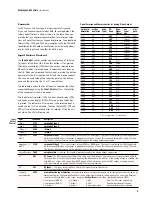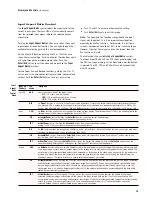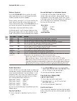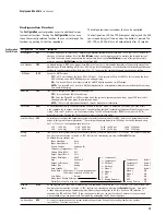
Initial Set
-Up
On
ce you have installed the iScan HD
+
in
to your system, it must
be properly configured for the display device being driven. The
iScan HD
+
is shipped fr
om the factory with the following preset
default settings:
䊳
Input Select is set to A
UTO, to automatically detect
an active input in a pre-configured priority.
䊳
Th
e Analog Video output is selected.
䊳
Th
e output format is set to ATSC (DTV) 480p, with YPbPr
colorspace and bilevel sync on the luma signal.
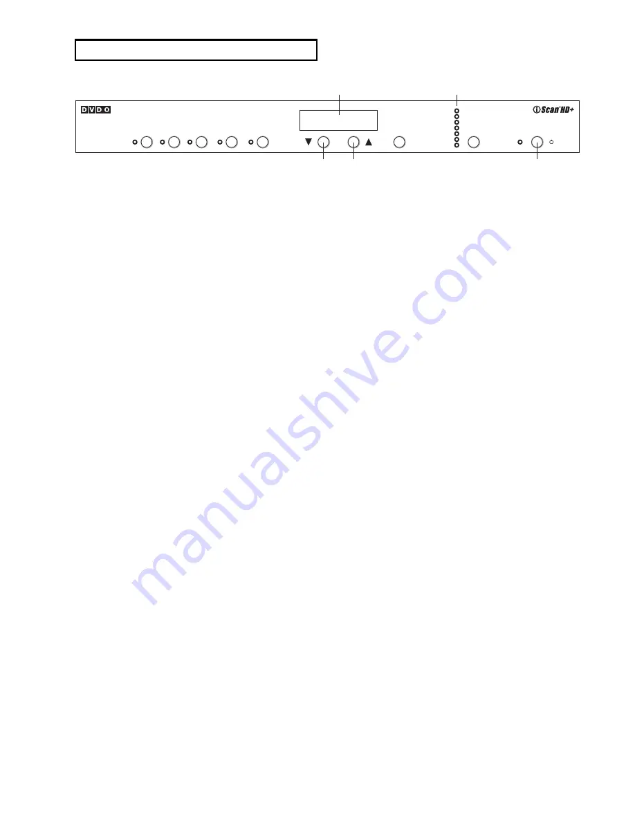
Use either the remote control or the front panel controls to
perform the initial setup of the iScan’s output. The front panel
buttons are used to perform the initial setup described below.
There are three ways to connect the iScan HD
+
output to a
display device. They are Analog Component, Analog RGB,
and DVI output.
Analog Component Output (YPbPr)
T
ypically, an HD15 (VGA-type) to 3-RCA connector cable is
needed for this configuration.
1.
Conn
ect the VGA end to the iScan’s Analog Video output.
2.
Conn
ect the 3 RCA connectors into the display device’s
Component Video input.
3.
Select th
e corresponding input on the display device.
You should get a picture. Now you are ready to set up your
display further with the remote control unit using the iScan
HD
+
’s on-scr
een display (OSD).
Note:
th
e iScan HD
+
featur
es a set of predefined formats that
you can choose from. These formats include colorspace and sync
signal type as shown in the Format table on page 9. If you
choose a format that requires RGB colorspace and separate
Hsync and Vsync, you need to manually change the colorspace
to YPbPr and sync type to bi-level or tri-level sync. Once this is
done, future format selections will always use the same color-
space and sync type that you reset the unit to.
Analog RGB Output
T
ypically either a VGA to VGA, a VGA to 5-BNC, or a VGA to
5-RCA cable is needed for this configuration.
1.
Conn
ect the HD15 (VGA) end to the iScan’s Analog output.
2.
Conn
ect the other end of cable to the display device’s
RGB input jacks.
3.
Chan
ge the sync type of the iScan HD
+
fr
om bi-level sync to
separate HSync and VSync. There are four separate sync
selections: positive Hsync and Vsync (H
+
V
+
), positive Hsyn
c
negative Vsync (H
+
V-), n
egative Hsync positive Vsync (H-
V
+
) an
d negative Hsync and Vsync (H-V-). Most formats
default to negative Hsync and Vsync. Refer to the Preset
Format table on page 9 for more details.
䊳
Push th
e
Output Setup
button un
til Sync Type is
selected and the front panel display (FPD) shows ‘SYNC’.
䊳
Pr
ess the
▼
button to see th
e sync type ‘BI’
(for bi-level sync).
䊳
Pr
ess the
▼
button to g
o to the next sync type.
䊳
Repeat this step to select th
e desired sync type.
䊳
Push th
e
Output Setup
button to e
xit the menu.
4.
Chan
ge the colorspace from Component YPbPr to RGB
䊳
Push th
e
Output Setup
button again. Th
e FPD shows
‘COLR’ for colorspace selection.
䊳
Pr
ess the
▼
button. Th
e FPD shows ‘YUV’, which is the
current colorspace (Component YPbPr).
䊳
Pr
ess
▼
button again to select th
e ‘RGB’ colorspace.
䊳
Push th
e
Output Setup
button to e
xit the menu.
You have now configured the iScan HD
+
to output 480p in RGB
colorspace, with separate Hsync and Vsync signals. Set up your
display further with the remote control unit using the iScan
HD
+
’s on-scr
een display (OSD).
Note:
Th
e actions above result in the iScan HD
+
always usin
g
RGB for colorspace and separate Hsync and Vsync signals regard-
less of format selection.
DVI Output
1.
Conn
ect the DVI cable from the DVI output of your iScan
HD
+
to th
e display device.
2.
Push th
e
Output Setup
button on
ce.
3.
Th
e FPD will show ‘A/D’ for analog or digital video output
choices.
4.
Push th
e
▼
button on
ce. The FPD will now display ‘ANLG’
for Analog Video output.
5.
Push
▼
button again. Th
e FPD will now show ‘DVIV’ for DVI
with Video levels.
6.
Y
ou should now see a picture on your display device.
7
D I S P L
AY S A N D C O N T R O L S
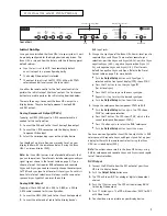
Front Panel Display (FPD)
Down
Up
Output Setup Indicators
On/Standby
Input
Select
Input
Aspect
Ratio
Picture
Control
Input
Adjust
Configuration
Adjust
Enter/Exit
Analog/ Digital
Format/Resolution
Aspect Ratio
Sync Type
Colorspace
Framelock
Display Profile
High Resolution Video Scaling Engine by Anchor Bay Technologies
Power
Output
Setup
On/Remote
Standby
Fr
ont of Unit


