Output Signal Connections
Th
ere are two output connectors on the back of the iScan HD
+
:
1) 15-pin HD15 Analog Output (VGA-type)
2) DVI Digital Video Output (with HDCP)
Use the 15-pin HD15 ouput of the iScan HD
+
to in
terface
to displays with a Component or VGA input. Use the DVI output
of the iScan HD
+
to in
terface to displays equipped with the
DVI interface.
P
ower Supply Input
Th
e iScan HD
+
com
es with a 6V@5A AC to DC converter power
supply, which accepts 100-240 VAC at 50/60Hz. Connect this to
the ‘DC In’ port on the back of the iScan HD
+
.
IMPORT
ANT: Use
only the power supply that came with your iScan HD+, or a
replacement procured directly from Anchor Bay Technologies.
Display Input Connectors
Th
ere are a number of different connectors used on displays,
such as RCA, 15-pin HD15 (VGA-type), BNC and DVI connectors.
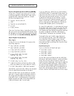
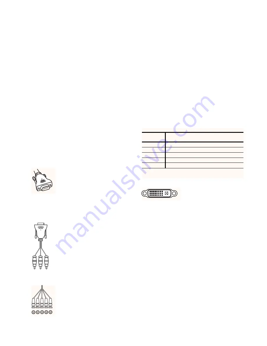
HD15 (VGA-type) Connector
Th
e VGA cable/connector is commonly used
in PC applications and should be readily
available in any computer or electronics store.
Select a well-shielded high-quality cable to
reduce reflections and other degrading effects on
the video signal. Most multimedia TVs/displays with progressive
scan capability will have an input of this type and should
accept both YUV and RGB color formats.
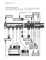
Component (YPbPr ) Input with RCA Jacks
M
ost displays with Component video inputs
will have three RCA jacks for YPbPr video signal
connections. Use the DVDO Precision HD15 to
3-RCA Component Video Cable (ABT part number
11-2001-01) to connect to these displays.
You can find it on our website at
www
.dvdo.com/pro/pro_acc.html
Conn
ect the three signal lines to the correspond-
ing color RCA jacks on your display.
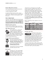
BNC Connectors
M
any displays such as home theater projectors
have five BNC connectors instead of an HD15
connector. For these displays, use an adapter
cable to convert from VGA to the BNC connectors
used on the display. These adapter cables are
readily available through most home theater
retailers and have a VGA connector on one end and BNC
connectors on the other. The BNC end of the cable will usually
have five connectors (labeled R, G, B, Hsync, and Vsync),
although not all will necessarily be needed for every display.
Please refer to your display’s specifications to determine which
input signals it requires. If your display device accepts
Component video (YPbPr), then you will not need the H and V
lines since these sync signals are actually part of the informa-
tion in the ‘Y’ signal. If your display device requires RGBS, then
this is Composite Sync, which is sent on the H (white/gray)
line. Displays that require RGBHV will require all 5 BNC connec-
tors. Hsync is sent on the white/gray wire, and Vsync is sent on
the yellow/black wire.
Below is a table showing the signal mappings for each wire of
the BNC cable.
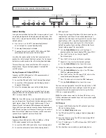
DVI Digital Video Input
Th
e DVI digital video connector is
used on many newer digital TVs and
is similar in functionality to the
analog VGA connector except that the video signal is transmit-
ted digitally from the iScan HD
+
to th
e display device. This
provides the highest possible quality video image from the iScan
HD
+
to th
e display. Many displays also support the High-band-
width Digital Content Protection (HDCP) specification across
the DVI interface. Displays with a DVI/HDCP input will show
protected content from the iScan HD
+
DVI output.
Once you have the iScan HD
+
conn
ected to your home theater
system, there are several configuration parameters that you may
adjust to output the proper signal format for your display device
and optimize the image to your personal preferences.
6
Installation and Set-Up
(continued)
Input T
ype
Wir
e Color
RGB/HV
RGBS
YPbPr
YUV/HS
(Component)
Red
R (Red)
R (Red)
Pr
U
Gr
een
G (Gr
een)
G (Green)
Y
Y
Blue
B (Blue)
B (Blue)
Pb
V
White or Gr
ay
H syn
c
Composite sync No Connect
H sync
Y
ellow or Black
V syn
c
No Connect
No Connect
V sync


