Formats
For DVI output, th
e Sync type is always separate Hsync and
Vsync, and the colorspace is always RGB. For analog output, the
factory default format is 480p as shown in the table. Once you
override the sync and colorspace selection, future format selec-
tions will not affect the sync type and colorspace. The predefined
formats 720p, 1080i and 1080p are compliant with the CEA-861B
specification for DVI output. Each format has two timing modes,
one for 50Hz inputs and the other for 60Hz inputs.
Input Select Control
Th
e
Input Select
con
trol enables you to select one of the nine
(9) inputs of the iScan HD
+
. Wh
en this button is first pressed,
the front panel display (FPD) shows the current selected input.
When this button is pressed again, it selects the next input on
the list. When you’ve reached the last input, pressing the button
again selects the first input on the list and the process repeats.
You can also cycle through the inputs by pushing this button
once and then pressing the
▼
or
▲
arr
ow buttons.
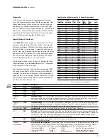
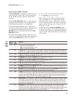
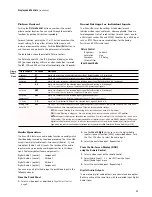
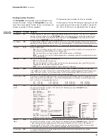
The table below shows the list of inputs in the order that they
are cycled through using the
Input Select
button. Th
e location
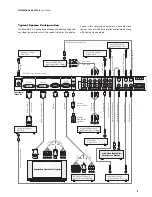
of the connectors is shown on page 4.
The Input Select indicator (LED), the front panel display (FPD)
and the on-screen display (OSD) will turn on when the button
is pressed. The indicator will turn green if the selected input is
active and red if it is not active. The Input Select LED, FPD and
OSD will turn off automatically after 30 seconds. If the input is
not active, the LED will remain red.
9
Input
Select
Control
Displays and Controls
(continued)
Horizontal
Resolution
Vertical
Resolution
Scan
Type*
FPD
shows
Sync
Signal
Line(s)
Sync
Signal
Type
Color-
space
720
480
P
480P
Y
Bi-level
YPbPr
1920
540
P
540P
Y
Tri-level
YPbPr
720
576
P
576P
Y
Bi-level
YPbPr
1280
720
P
72P5
Y
Tri-level
YPbPr
1280
720
P
72P6
Y
Tri-level
YPbPr
1920
1080
I
18I5
Y
Tri-level
YPbPr
1920
1080
I
18I6
Y
Tri-level
YPbPr
1920
1080
P
18P5
Y
Tri-level
YPbPr
1920
1080
P
18P6
Y
Tri-level
YPbPr
640
480
P
V
GA
H-V-
-
RGB
800
600
P
SV
GA
H
+
V
+
-
RGB
1024
768
P
XG
A
H-V-
-
RGB
1280
1024
P
S
XGA
H-V-
-
RGB
852
480
P
PLA1
H-V-
-
RGB
852
576
P
PLA2
H-V-
-
RGB
1366
768
P
PLA3
H-V-
-
RGB
1280
768
P
PLA4
H-V-
-
RGB
1024
1024
P
PLA5
H-V-
-
RGB
1024
852
P
PLA6
H-V-
-
RGB
1024
576
P
DLP1
H-V-
-
RGB
848
600
P
DLP2
H-V-
-
RGB
1365
1024
P
DIL1
H-V-
-
RGB
1400
1050
P
DIL2
H-V-
-
RGB
1400
788
P
DIL3
H-V-
-
RGB
960
540
P
LCD1
H-V-
-
RGB
1280
960
P
QU
A1
H-V-
-
RGB
1440
960
P
QU
A2
H-V-
-
RGB
1440
1152
P
QU
A3
H-V-
-
RGB
*
P = pr
ogressive; I = interlace
Pr
eset Formats and Characteristics for Analog Video Output
Input
FPD shows
Description
Vi
deo 1
VID1
Composite Video 1
Vi
deo 2
VID2
Composite Video 2
S-Vi
deo 1
SVD1
S-Video 1
S-Vi
deo 2
SVD2
S-Video 2
Compon
ent 1 /
RGBS 1
COM1
Component Video 1
- This input accepts eith
er a YPbPr or RGBS signal. The input is configured for YPbPr by default,
and switches to RGB when a connector is plugged into the Sync 1 input. This input will accept 480i, 480p, 576i and
576p formats. All other formats will be passed through to the analog output unprocessed.
Component 2 /
RGBS 2
COM2
Component Video 2
- This input accepts eith
er a YPbPr or RGBS signal. The input is configured for YPbPr by default,
and switches to RGB when a connector is plugged into the Sync 2 input. This input will accept 480i, 480p, 576i and
576p formats. All other formats will be passed through to the analog output unprocessed.
Analog Passthru
P
ASS
Analog Passthru
is selected
. This signal is passed through to the Analog Output unprocessed.
DVI
D
VI
DVI Input
- Th
e DVI input accepts 480p, 576p, 720p and 1080i formats. If the content is copy-protected by HDCP,
the iScan HD
+
will output th
e processed signal on the DVI output with HDCP or if the analog output is selected, the
iScan HD
+
will output blue scr
een. Non HDCP signals will be output on either the DVI output or analog output.
Other input formats are passed through to the DVI output unprocessed.
SDI*
SDI
SDI Input.
– This input accepts eith
er a 480i or 576i signal from an SDI source.*
*
SDI Video Input Module required.
A
utomatic
Input Selection
A
UTO
Automatic active input selection -
A
utomatically selects an input from among all currently active inputs based on an
internal priority list. The factory default list is shown below from highest to lowest priority. You can assign different
priorities to the iScan HD
+
’s vi
deo inputs using the
Configur
ation
con
trol then selecting AutoSource (IPSL).
Note: The DVI input and Analog
Passthru functionality is depen-
dent on which output is selected.
1- Compon
ent / RGBS 1
2- Component / RGBS 2
3- S-Video 1
4- S-Video 2
5- Video 1
6- Video 2
7- DVI
8- SDI*
9- Analog Passthru


