Configuration Control
Th
e
Configur
ation
con
trol provides access to additional impor-
tant control functions. Pushing the
Configur
ation
button on
ce
shows the currently selected function. You can cycle through the
functions by pushing this button repeatedly.
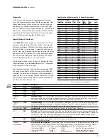
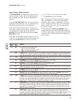
The table below shows selections that can be controlled.
The Configuration LED, the FPD (front panel display) and the OSD
(on-screen display) will turn on when the button is pressed. The
LED, FPD, and OSD will turn off automatically after 30 seconds.
13
Display
s and Controls
(continued)
Configur
ation
FPD shows Description
T
est Patterns
TEST
This m
enu allows you to select the 27 different test patterns available in the iScan HD
+
. Push th
e
▲
or
▼
button to
select one of the test patterns. Push the
T
est Patterns
button on th
e remote control to activate the selected test pat-
tern. Push the button again to deactivate the test pattern. Refer to the
T
est Patterns
secti
on of this guide for more
details on using the
T
est Patterns
featur
e of the iScan HD
+
A
uto Standby
STB
Y
Th
e default setting is
OFF
, whi
ch means iScan HD
+
will always be in A
ctive mode regardless of the activity state of the
selected input. If Auto Standby is
ON
, iScan HD
+
will g
o into Standby mode 30 seconds after the selected input becomes
inactive. To see the current setting, first press
▲
or
▼
. Th
en press the same button again to change the setting.
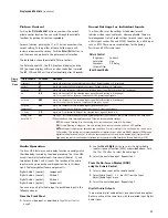
HDCP Mode
HDCP
Th
ere are 3 HDCP modes:
OFF:
HDCP is disabled at th
e iScan HD
+
's DVI input. Som
e sources will turn off HDCP in this case and the iScan
HD
+
will d
rive a non-HDCP DVI display or an analog display.
ON:
Th
e iScan HD
+
will con
tinuously look for a HDCP display device on its DVI output.
A
UTO:
Th
e iScan HD
+
will look f
or a HDCP display device for a limited time, after which it will output blue screen
to a non-HDCP display.
Power LED
PLED
Allows you to confi
gure the behavior of the Power LED.
OFF:
T
urns the Power LED off at all times
ON:
T
urns the Powe LED on. LED turns blue when the system is processing the an input signal. LED turns red in
standby mode. LED turns green in pass-through mode.
A
UTO:
LED turn
s off after approximately 30 seconds without user interaction.
User Mode
USRM
Y
ou have limited access to the output timing controls in ‘Normal’ mode. In ‘Advanced’ user mode, you have access
to the complete set of output timing controls. See the section entitled “Customizing the Output Video Timing for your
Display”. Push the
▼
button to see th
e current setting. The FPD will display either ‘NORM’ for normal or ‘ADV’ for
advanced user level. Pushing the
▼
button again selects th
e alternate mode.
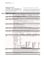
Serial Port Rate
R232
Th
e serial port is used by the automation system controllers to control the iScan HD
+
. Refer to th
e Automation Control
section of this guide for more information. The serial port baud rate defaults to 19200 bps but can be changed using
the
▲
or
▼
button. Th
e supported baud rates are:
1.2K
1200 bps
4.8K
4800 bps
14.4K
14400 bps
38.4K 38400 bps
2.4K
2400 bps
9.6K
9600 bps
19.2K
19200 bps
57.6K 57600 bps
Factory
Default
FCTD
Allows you to r
eset system settings to the factory default. First press either the
▲
or
▼
button. Th
e FPD will show ‘NO’.
Then press the same button to switch to ‘YES’. Confirm this selection by pressing the
Enter/Exit
button.
The default factory settings are:
Input Selection :
Auto
Input Aspect Ratio :
16:9
Picture Controls :
midrange (0)
Sharpness (Component) : Off
Chroma Filter (CUEC) :
Off
Output Aspect Ratio :
16:9
Output Resolution :
480P
Sync :
Sync on Y
Output Color Space :
YPbPr
Output Type :
Analog
Auto Standby :
Off
Frame Rate : 60Hz input - 1:1 source-locked output
50Hz input - unlocked at 59.94 Hz
User Mode :
Normal
Video Input Priority Settings :
Digital Audio Input Assignment :
Software
Update
SWUP
Y
ou can upgrade your iScan HD
+
firm
ware using this command. First press the
▲
or
▼
button. Th
e FPD will show ‘NO’.
Then press the same button to switch to ‘YES’. Confirm this selection by pressing the
Enter/Exit
button. Car
e must
be taken before performing a firmware upgrade. Make sure you really want to do this. Once the ‘YES’ selection is
confirmed, the FPD will show ‘LOAD’. If you change your mind, you can wait for about 5 minutes for the command
to be cancelled or you can power cycle the system by unplugging the DC Power input jack.
The About Box
INFO
This sh
ows information about the system including Input Status, Output Status and System Version number.
Press the
▲
or
▼
button to activate
.
Configur
ation
Control Menu
1– Compon
ent 1
2– Component 2
3– S-Video 1
4– S-Video 2
5– Video 1
6– Video 2
7– DVI
8– SDI
9– Analog Passthru
Component 1
- Audio 1
Component 2
- Audio 4
S-Video 1
- Audio 2
S-Video 2
- Audio 3
Video 1
- Off
Video 2
- Off
DVI
- Off
SDI
- Off
Analog Passthru - Off


