background image

English (GB)

13

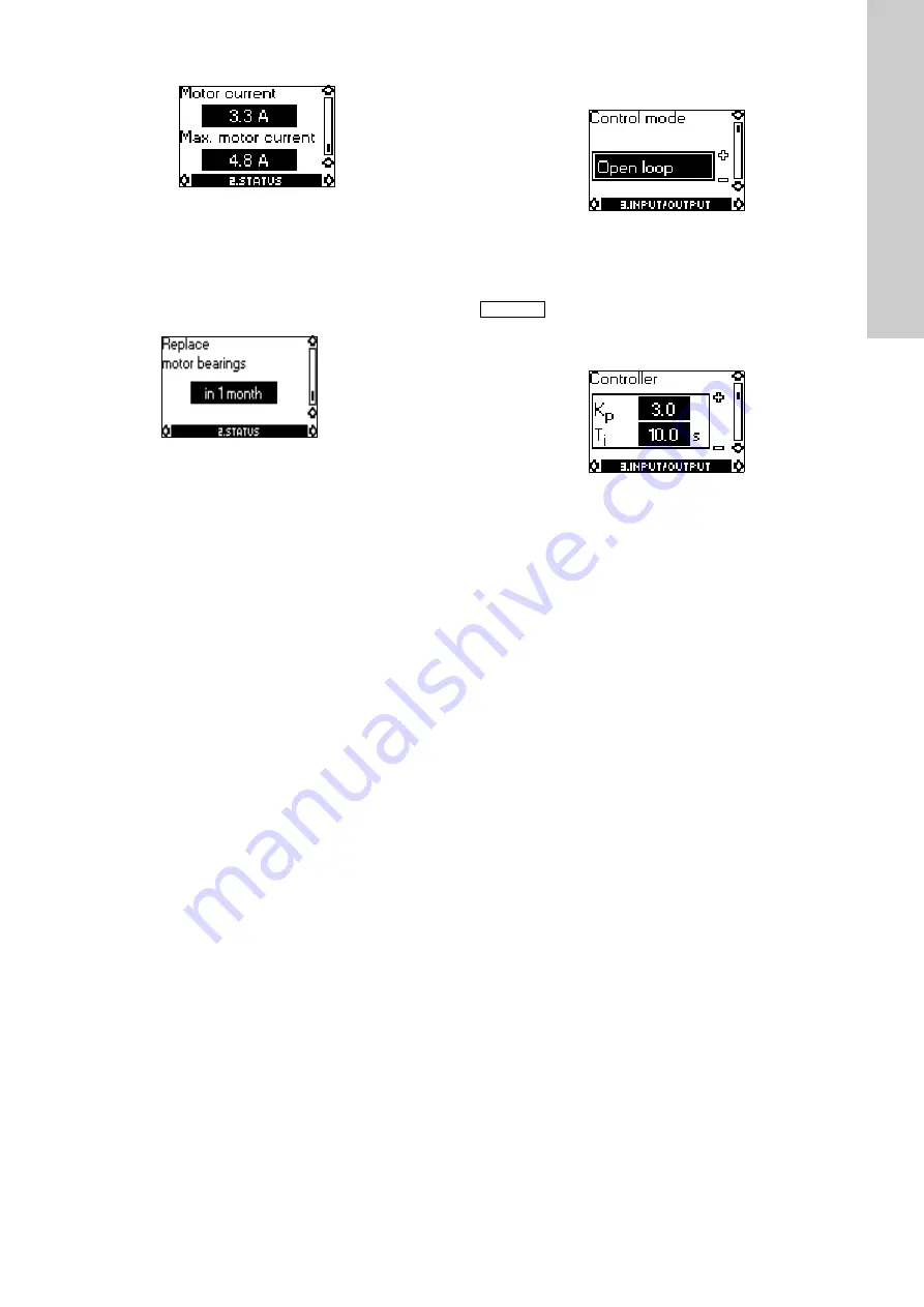
10.2.7 Display of motor current

Tolerance: ± 5 % 

Motor current 

indicates the actual motor input current from 

the frequency converter.

Max. motor current

 indicates the maximum motor current 

limit.

10.2.8 Time till replacement of motor bearings 

(only three-phase motors)

This display shows when to replace the motor bearings. 
The controller monitors the operating pattern of the pump and 
calculates the period between bearing replacements. 
The displayable values are these:
• in 2 years
• in 1 year
• in 6 months
• in 3 months
• in 1 month
• in 1 week
• Now!

10.3 Menu INPUT/OUTPUT 

10.3.1 Selection of control mode

Select one of the following control modes: 

Closed loop

,

Open loop

10.3.2 Setting of controller

In this display, the gain (K

p

) and the integral-action time (T

i

) of the 

built-in PI controller can be set if the factory setting is not the 
optimum setting:
• The  gain  (K

p

) is set within the range from 

0.1

 to 

20

.

• The integral-action time (T

i

) is set within the range from 

0.1

 to 

3600 s

If 

3600 s

 is selected, the controller will function as a P 

controller. 

Setting the PI controller:

1. Start the motor and adjust the system so that the motor is 

operating in the typical operating situation.

2. Set the integral-action time (T

i

) to 3600 s.

3. Increase the gain (K

p

) until the motor operation gets unstable, 

i.e. until the actual value starts fluctuating, see section 

10.2.3 Display of actual value

. Instability can also be heard 

because the motor starts adjusting the speed up and down. 
Some systems react slowly, e.g. during temperature control. 
Therefore, several minutes may pass before the motor 
operation gets unstable.

4. Set the gain (K

p

) to half the value at which the motor got 

unstable. Then the gain has been set.

5. Reduce the integral-action time (T

i

) until the motor gets 

unstable.

6. Set the integral-action time (T

i

) to the double value of the 

value at which the motor got unstable. The PI controller has 
now been set.

Inverse control:

It is possible to set the controller to inverse control (if the setpoint 
is increased, the speed will be reduced). In the case of inverse 
control, the gain (K

p

) must be set within the range from 

-0.1

 to 

-20

.

Note

If the motor is connected to a bus (see section 

13. Bus signal

), it is not possible to select the 

control mode via the R100.

Содержание VT Booster Set

Страница 1: ...VT Booster Set O M Manual...

Страница 2: ...trol Panel Wiring Diagrams 12 2 3 HAND OFF AUTO Switch Operation 16 2 4 Installation and Commissioning VT Booster Sets 17 3 User Maintenance and Troubleshooting 22 3 1 Routine User Maintenance 23 3 2...

Страница 3: ...1 Important Health Safety Information Page 3 VT Booster Set...

Страница 4: ...edefined at the beginning of their manual PLEASE READ THE FOLLOWING INFORMATION WHICH IS PROVIDED FOR YOUR SAFETY Danger Denotes attention to the possibility of the risk of personal injury or damage t...

Страница 5: ...Note Denotes attention to an important factor applicable to the action being performed Page 5 VT Booster Set...

Страница 6: ...nual must be read before working on the equipment Installation operating and maintenance must only be carried out by suitably trained qualified personnel Normal safety precautions must be taken and ap...

Страница 7: ...mps to maintain the running pressure of the system to an acceptable level Pump Servicing Familiarise yourself with the relevant contents of this manual Installation maintenance and repair work must on...

Страница 8: ...perly authorised personnel When connecting external control wires care must be taken not to short circuit adjacent components Bare cable ends which are not in use must be insulated THE SYSTEM MUST ONL...

Страница 9: ...ure 35 C domestic uses EN 60335 2 41 40 C for other purposes Minimum pumped liquid temperature 1 C to avoid icing Operating ambient temperature 5 C to 40 C for indoor installation CEI EN 60439 1 Relat...

Страница 10: ...2 System Information Installation and Commissioning Page 10 VT Booster Set...

Страница 11: ...2 1 Booster Set Components VT Booster Set Components Page 11 VT Booster Set...

Страница 12: ...2 2 Control Panel Wiring Diagrams Twin Pump Wiring Diagram Single Phase Page 12 VT Booster Set...

Страница 13: ...Twin Pump Wiring Diagram 3 Phase Page 13 VT Booster Set...

Страница 14: ...VT3 Single Phase Control Panel Wiring Diagram VR VASCO Cold Water Booster Sets Page 14 VT Booster Set...

Страница 15: ...VR VASCO Cold Water Booster Sets Page 15 VT Booster Set...

Страница 16: ...VT3 Three Phase Control Panel Wiring Diagram Page 16 VT Booster Set...

Страница 17: ...Page 16a VT Booster Set...

Страница 18: ...ficiently if further re commissioning is carried out on site Please note that engineer visits by Dutypoint are priced at one visit to commission one pump set If there are multiple units on a site spec...

Страница 19: ...d for the installation e g Earth Loop Impedance Insulation Tests etc 5 Carry out any other pre start checks recommended by the pump manufacturer Refer to the pump manual in Appendix A of this manual D...

Страница 20: ...pump bleed point This procedure should be carried out individually for each pump in the Pumpset 1 This procedure should be carried out individually for each pump in the Pumpset 2 Open all valves on th...

Страница 21: ...priate step by step setting up procedures contained in the manual ensuring that any data required to be entered by the end user is accurately inserted where requested If in doubt please call Dutypoint...

Страница 22: ...in the system to a point where one pump only cannot maintain the required output Verify that the Assist Pump starts and runs together with the Duty Pump and that the desired pressure is duly restored...

Страница 23: ...3 User Maintenance and Troubleshooting Page 22 VT Booster Set...

Страница 24: ...any maintenance work until 1 YOU HAVE READ THE SAFETY SECTION AT THE BEGINNING OF THIS MANUAL 2 YOU ARE DRESSED IN THE CORRECT PROTECTIVE CLOTHING 3 YOU HAVE ALL NECESSARY SAFETY EQUIPMENT TO HAND Ref...

Страница 25: ...oning procedure to verify correct safe operation Detailed Pump Maintenance Please refer to the manufacturer s document Detailed Controller Maintenance Please refer to the appropriate manufacturer s do...

Страница 26: ...d rectify Blown fuse Check and rectify Overload trip Check and if necessary reset the overload trip value For control panel information refer to Section 2 For pump and controller manufacturer s inform...

Страница 27: ...Check and rectify The rotating part s of the pump is are partially or completely obstructed e g impeller obstructed by foreign matter Strip the pump to inspect and rectify For pump and controller manu...

Страница 28: ...ge flow rate too high Reduce by the discharge flow rate by increasing the discharge back pressure slightly progressively closing a manual isolating valve on the discharge side then try again Overload...

Страница 29: ...RN Pump O M Ap 1 2 Grundfos CRE CRIE CRNE SPKE MTRE CME Controller O M Up to 2 2kW This Controller O M covers models in the following range VT2 3 4 0511 1022 Ap 1 3 Grundfos MGE 71 MGE 80 MGE 90 MGE 1...

Страница 30: ...Ap 1 1 Grundfos CR CRI CRN Pump O M CR CRI CRN Installation and operating instructions GRUNDFOS INSTRUCTIONS Page 29...

Страница 31: ...009 Applies only to three phase Grundfos motors marked IE2 or IE3 See motor nameplate Standard used EN 60034 30 2009 Ecodesign Directive 2009 125 EC Water pumps Commission Regulation No 547 2012 Appli...

Страница 32: ...ical data G6 5 8 Frequency of starts and stops G6 5 9 Dimensions and weights G6 5 10 Sound pressure level G6 6 Installation G6 6 1 Foundation G7 6 2 Vibration dampening G7 6 3 Outdoor installation G8...

Страница 33: ...igher rated output Fig 2 Motor output depends on temperature altitude Example Figure 2 shows that the load of an IE3 motor at an ambient temperature of 70 C must not be loaded more than 89 of the rate...

Страница 34: ...fig E on page 18 tm liquid temperature Hs Safety margin minimum 0 5 metres head If the calculated H is positive the pump can operate at a suction lift of maximum H metres head If the calculated H is n...

Страница 35: ...C 0 10 20 30 Qmin Step Action 1 TM02 0013 3800 Arrows on the pump base show the direction of flow of liquid through the pump 2 TM00 2256 3393 This information is stated on page 17 port to port length...

Страница 36: ...taken as 2 200 kg m3 In installations where noise less operation is particularly important a foundation with a mass up to 5 times that of the pump is recommended The foundation must be provided with b...

Страница 37: ...care should be taken to ensure that persons cannot accidentally come into contact with hot surfaces TM04 0361 0608 CR CRI CRN Base Nm Flange Nm 1s to 5 40 50 60 10 to 20 50 60 70 32 to 150 70 70 80 Pu...

Страница 38: ...e motors must be connected to a motor protective circuit breaker Warning Before removing the terminal box cover and before removing dismantling the pump make sure that the power supply has been switch...

Страница 39: ...r further information please contact the frequency converter or motor supplier Other motor makes than those supplied by Grundfos Please contact Grundfos or the motor manufacturer 8 Start up Follow the...

Страница 40: ...vent screw and replace the drain plug until the pump is to be used again CR CRI CRN 1s to 5 Before replacing the drain plug in the base screw the bypass valve out against the stop See fig 20 Fig 20 L...

Страница 41: ...ng of the pump f Motor protective circuit breaker setting is too low Set the motor protective circuit breaker correctly 3 Motor protective circuit breaker trips out occasionally a Motor protective cir...

Страница 42: ...Appendix G13 Appendix 1 NPSH TM02 7387 3403 TM02 7126 2703 TM01 9882 3801 TM02 7127 2703 TM01 9883 3300 TM01 9884 3801 TM02 7125 2703...

Страница 43: ...Appendix 14...

Страница 44: ...to 120 C CR CRN 64 6 2 64 8 1 30 bar 30 C to 120 C CR CRN 90 1 1 90 4 16 bar 30 C to 120 C CR CRN 90 5 2 90 6 30 bar 30 C to 120 C CR CRN 120 30 bar 30 C to 120 C CR CRN 150 30 bar 30 C to 120 C 60 H...

Страница 45: ...CRN 5 CR CRI CRN 5 2 CR CRI CRN 5 16 CR CRI CRN 5 18 CR CRI CRN 5 36 10 bar 15 bar CR CRI CRN 5 2 CR CRI CRN 5 9 CR CRI CRN 5 10 CR CRI CRN 5 24 10 bar 15 bar CR CRI CRN 10 CR CRI CRN 10 1 CR CRI CRN...

Страница 46: ...00 125 125 125 125 H mm 75 75 75 75 75 75 75 75 80 80 90 90 90 90 105 105 140 140 140 140 140 140 180 180 180 180 L mm 250 250 250 250 250 250 250 250 280 280 300 300 300 300 320 320 365 365 365 365 3...

Страница 47: ...Fig D Airborne noise emitted by pumps with motors fitted by Grundfos Motor kW 50 Hz 60 Hz 0 37 50 55 0 55 50 53 0 75 50 54 1 1 52 57 1 5 54 59 2 2 54 59 3 0 55 60 4 0 62 66 5 5 60 65 7 5 60 65 LpA dB...

Страница 48: ...Appendix G19 CR CRI CRN 1s 1 3 and 5 Fig F A TM02 0459 4600 B TM02 0460 4600 C TM02 1051 0501 D TM02 1052 0501 M6 13 Nm M8 31 Nm M10 62 Nm 0 5x x M5 2 5 Nm...

Страница 49: ...Appendix G20 CR CRI CRN 10 15 and 20 Fig G A TM02 1045 0501 B TM02 8500 0304 C TM02 7923 4403 D TM02 0459 4600 E TM02 8542 0404 F TM02 8515 0304 M5 2 5 Nm 1 2 M6 13 Nm M8 31 Nm M10 62 Nm...

Страница 50: ...Appendix 21...

Страница 51: ...Appendix 22...

Страница 52: ...36a Nut 37 O ring gasket 38 O ring 38a O ring 44 Inlet part complete 45 Neck ring 45a Neck ring complete 47 Bearing ring 47a Bearing with driver 47b Bearing ring rotating 47c Bush 47d Retaining ring...

Страница 53: ...1 3 and 5 TM02 0455 3403 6 56 203 201 38 25 6 6 26 28 36a 2 10a 8 9 10 5a 65 45 4 65 45 36 66a 76a 76 18 64 66 49 47a 64c 67 7 7a 23 7 7a 100 60 50a 28 2 6 37 6 51 37 38 25 39 12 35 105 100 49 64a 45...

Страница 54: ...2 35 76a 10 9 8 10a 28 105 2 66a 36 76 18 100 26 60 37 45 65 4a 4 65 45 64 3 69 61 64a 64d 44b 26c 26b 2 201 203 56 6 47a 44a 65 45 64b 64c 66 67 64 45 65 4 25 38a 38 80 26a 77 37 55 10a 8 9 10 1 28a...

Страница 55: ...Appendix 26...

Страница 56: ...Appendix 27...

Страница 57: ...Appendix G28 Appendix 1 Start up 1 TM01 1403 4497 2 TM01 1404 4497 3 TM01 1405 4497 4 TM01 1406 4497 5 TM01 1407 4497 6 TM01 1408 4497 7 TM01 1409 4497 8 TM01 9988 3600...

Страница 58: ...rrect direction of rotation of the pump on the motor fan cover 4 Start the pump and check the direction of rotation 5 Vent the pump by means of the vent valve in the pump head At the same time open th...

Страница 59: ...ontroller O M covers models in the following range VT2 3 4 0511 1022 CRE CRIE CRNE SPKE MTRE CME Installation and operating instructions supplement Functional descriptions GRUNDFOS INSTRUCTIONS Instal...

Страница 60: ...24 7 16 LiqTec LiqTec function 24 7 17 Stop function Low flow stop function 25 7 18 Pipe filling function 26 7 19 Pulse flowmeter Pulse flowmeter setup 27 7 20 Ramps 27 7 21 Standstill heating 27 7 2...

Страница 61: ...econds until the light field starts flashing To change back press continuously until the desired setpoint is indicated Example Pump set to maximum curve Figure 4 shows that the top light field is flas...

Страница 62: ...anel The pumps can be fitted with the advanced control panel as an option Fig 6 Advanced control panel TM05 4897 2812 Note If you have stopped the pump by pressing and the Stop text on the control pan...

Страница 63: ...l go directly to the Settings display for the selected parameter 2 Status This menu shows the status of the pump and system as well as warnings and alarms 3 Settings This menu gives access to all sett...

Страница 64: ...nt Speed Acc flow and specific energy Power and energy consumption Measured values Analog input 1 Analog input 2 Analog input 3 1 1 Pt100 1000 input 1 1 1 Pt100 1000 input 2 1 1 Analog output 1 1 Warn...

Страница 65: ...1 1 Controller settings 7 11 Controller Controller settings 20 Operating range 7 12 Operating range 21 Setpoint influence 7 13 External setpoint function 21 Ext setpoint infl 7 13 External setpoint fu...

Страница 66: ...tore actual settings 7 33 Store settings Store actual settings 29 Recall stored settings 7 34 Recall settings Recall stored settings 29 Run start up guide 7 37 Run start up guide 30 1 Only available i...

Страница 67: ...ation Radio communication can take place at distances up to 30 metres The first time Grundfos GO communicates with the pump you must enable communication by pressing or on the pump control panel Later...

Страница 68: ...nput 3 1 Digital input 1 Digital input 2 1 Digital in output 3 Digital in output 4 1 Fitted modules Pump 1 2 Pump 2 2 Pump 3 2 Pump 4 2 Settings CRE CRIE CRNE SPKE MTRE CME Multipump system Section Pa...

Страница 69: ...ed 7 15 Limit exceeded function 24 Limit 2 exceeded Alternating operation time 2 7 44 Multi pump setup Setup of multi pump system 31 Time for pump changeover 1 2 Standstill heating 7 21 Standstill hea...

Страница 70: ...y setting See section 16 Factory settings 7 4 Control mode Possible control modes Constant pressure Const pressure Constant temperature Const temp Constant differential pressure Con diff press Constan...

Страница 71: ...external pressure sensors as shown in the examples below Fig 15 Constant differential pressure Controller settings For recommended controller settings see section 7 11 Controller Controller settings...

Страница 72: ...w in the system independently of the head See fig 18 Fig 18 Constant flow rate This control mode requires a flow sensor as shown below Fig 19 Constant flow rate Controller settings For recommended con...

Страница 73: ...mode if you wish to control a value which is not available in the Control mode menu Connect a sensor measuring the controlled value to one of the analog inputs of the pump The controlled value will be...

Страница 74: ...y the sensor connected to the actual analog input See fig 23 Fig 23 Overview of sensor locations Unit Available measuring units Electrical signal Select signal type 0 5 3 5 V 0 5 V 0 10 V 0 20 mA 4 20...

Страница 75: ...maximum speed External fault When the input is activated a timer will be started If the input is activated for more than 5 seconds the pump will be stopped and a fault will be indicated This function...

Страница 76: ...ump is running Warning There is an active warning Limit 1 exceeded When the Limit 1 exceeded function is activated the signal relay is activated See section 7 15 Limit exceeded function Limit 2 exceed...

Страница 77: ...condary parameters in the system If the limit is exceeded an output warning or alarm is activated Flow rate Reading is a percentage of the range between 0 and 200 of the nominal flow Qnom Factory sett...

Страница 78: ...In heating systems an increase in pump performance will result in a rise in temperature at the sensor 2 In cooling systems an increase in pump performance will result in a drop in temperature at the...

Страница 79: ...and an external setpoint of 60 the actual setpoint is 0 60 x 85 25 25 61 See fig 28 Fig 28 Example of setpoint influence with constant curve 7 13 1 Setpoint influence functions You can select these f...

Страница 80: ...op If the input signal is reduced below 85 the operating mode will be changed back to Normal See fig 32 Inverse with Min In the input signal range from 0 to 80 the setpoint is influenced inversely If...

Страница 81: ...u can also set one or two of the digital inputs to Predefined setpoints but this will limit the number of predefined setpoints available Example Figure 36 shows how you can use the digital inputs to s...

Страница 82: ...s speed to maximum Detection delay You can set a detection delay which ensures that the monitored parameter stays above or below a set limit in a set time before the Limit exceeded function is activat...

Страница 83: ...ce between start and stop pressures H and minimum flow In start stop operation the pressure will vary between the start and stop pressures See fig 38 In User defined mode Customised operating mode H h...

Страница 84: ...s been filled phase two begins 2 Pressure build up phase The system pressure is increased until the setpoint is reached The pressure build up takes place over a pressure build up time If the setpoint...

Страница 85: ...ve and the pump is in operating mode Stop a low AC voltage will be applied to the motor windings The applied voltage is not high enough to make the motor rotate but will ensure that sufficient heat is...

Страница 86: ...tion 16 Factory settings 7 26 Language This menu is only available in the advanced control panel In this menu you can select the desired language A number of languages is available Factory setting See...

Страница 87: ...tore the actual settings for later use in the same pump or in other pumps of the same type Advanced control panel In this menu you can store the actual settings for later use in the same pump 7 34 Rec...

Страница 88: ...ome Run with Constant curve Run with Constant pressure See section 7 4 Control mode Go to Assisted pump setup See section 7 41 Assisted pump setup Return to factory settings Applies only for pumps fit...

Страница 89: ...s The pumps in a multipump system communicate with each other via the wireless GENIair connection or the wired GENI connection A multipump system is set up via a selected pump i e the master pump firs...

Страница 90: ...two pumps with each other with a 3 core screened cable between the GENIbus terminals A Y B 2 Power on both pumps 3 Establish contact to one of the pumps with the Grundfos GO 4 Set up the needed analog...

Страница 91: ...p number 5 Select the Assist menu on one of the pumps and choose Setup of multi pump system 6 Press to continue 7 Select Wired GENIbus as the communication method to be used between the two pumps 8 Pr...

Страница 92: ...hermore you can set the pump to maximum speed by continuously pressing You can always set the pump to operation at maximum speed or to stop with Grundfos GO If two or more functions are enabled at the...

Страница 93: ...p stopped Two opposite red indicator lights flashing simultaneously Alarm Pump stopped The green indicator light in the middle flashes quickly four times This is a feedback signal which the pump gives...

Страница 94: ...Max Warning but the pump is running in Manual mode Yellow rotating Manual Warning but the pump was stopped via Stop command Yellow steady Stop Alarm but the pump is running Red rotating Normal Min or...

Страница 95: ...plastic holders fig 48 pos A and the connecting plug fig 48 pos B Press home the module using your fingers Fig 48 Align CIM module with plastic holders pos A and connecting plug pos B 6 Fit and tight...

Страница 96: ...label then place this on the terminal box See fig 51 Fig 51 Position of FCC label 12 Fit the terminal box cover fig 45 pos B and cross tighten the four mounting screws fig 45 pos A to a torque of 6 N...

Страница 97: ...n the motor nameplate See fig 53 Fig 53 Identification of control panel TM06 1889 3314 Variant Description FM 200 Standard functional module FM 300 Advanced functional module Env Type Serial no SF CL...

Страница 98: ...ver 4 Turn the plastic cover 180 Fig 57 Turning the plastic cover 5 Re position the plastic cover correctly on the four rubber pins pos C Make sure that the locking tabs pos A are placed correctly Fig...

Страница 99: ...5 Kp 0 5 0 5 0 5 Operating range 13 100 13 100 13 100 Page 21 Ramps Page 27 Ramp up 1 second 1 second 1 second Ramp down 3 second 3 second 3 second Number Pump number Page 28 Radio communication Activ...

Страница 100: ...Advanced Installation and operating instructions GRUNDFOS INSTRUCTIONS Ap1 3 Grundfos MGE 71 MGE 80 MGE 90 MGE 132 Controller O M More than 2 2kW This Controller O M covers models in the following ran...

Страница 101: ...gainst mains voltage transients 4 5 6 Supply voltage 4 5 7 Start stop of motor 4 5 8 Other connections 5 6 Electrical connection three phase motors 5 6 1 Mains switch 5 6 2 Protection against electric...

Страница 102: ...he flange can be turned 90 to both sides or 180 Fig 3 Drain holes MGE 90 to MGE 132 B3 mounting The motor has two plugged drain holes on the drive side The flange can be turned 180 B14 and B5 mounting...

Страница 103: ...ently pulled out of the cable entry For maximum backup fuse see section 17 1 Supply voltage Fig 6 Example of a mains connected motor with mains switch back up fuses and additional protection Fig 7 Mai...

Страница 104: ...kage may be 10 mA the demands on the earth connection are tightened The motor must be stationary and installed permanently Furthermore it must be connected permanently to the electricity supply In add...

Страница 105: ...e supply voltage and frequency are marked on the motor nameplate Please make sure that the motor is suitable for the electricity supply on which it will be used The wires in the motor terminal box mus...

Страница 106: ...he wires in the motor terminal box must be as short as possible 7 1 Bus connection cable 7 1 1 New installations For the bus connection a screened 3 core cable having a cross sectional area of min 0 5...

Страница 107: ...ed sensor Figure 17 shows that the light fields 5 and 6 are activated indicating a desired setpoint of 3 bar with a sensor measuring range from 0 to 6 bar The setting range is equal to the sensor meas...

Страница 108: ...s continuously until the desired setpoint is indicated Example Motor set to min frequency Figure 20 shows that the bottom light field is flashing indicating min frequency Fig 20 Min frequency duty 9 6...

Страница 109: ...divided into six parallel menus fig 22 0 GENERAL see operating instructions for the R100 1 OPERATION 2 STATUS 3 INPUT OUTPUT 4 FUNCTIONS 5 DRIVE The number stated at each individual display in fig 22...

Страница 110: ...If the motor is controlled via external signals or a bus this will be indicated in the display if setpoint setting is attempted In this case the number of possible settings will be reduced see section...

Страница 111: ...panel and press OK If a parameter e g speed should be called up continuously press OK constantly during the period in which the parameter in question should be monitored The tolerance of the displaye...

Страница 112: ...unction as a P controller Setting the PI controller 1 Start the motor and adjust the system so that the motor is operating in the typical operating situation 2 Set the integral action time Ti to 3600...

Страница 113: ...inputs Motor digital inputs see also fig 8 or 11 Terminals 1 and 9 digital input 2 Terminals 10 and 9 digital input 3 Terminals 11 and 9 digital input 4 The digital inputs can be set to different func...

Страница 114: ...ons and on the motor can be set to Active Not active 10 4 5 Allocation of motor number A number between 1 and 64 can be allocated to the motor or can be changed In connection with bus communication a...

Страница 115: ...a 10 5 3 Selection of direction of rotation Select the nominal direction of rotation of the motor when seen from the drive end Clockwise Anti clockwise The displayed direction of rotation will apply w...

Страница 116: ...n in the motor 11 External forced control signals The motor has inputs for external signals for the forced control functions Start stop of motor Digital function 11 1 Start stop input Functional diagr...

Страница 117: ...et motor operating parameters like setpoint operating mode etc At the same time the motor can via the bus provide status information about important parameters like actual value of control parameter i...

Страница 118: ...l flash rapidly TM00 7600 0304 TM02 8513 0304 Red Green Green Red Indicator lights Contact position for signal relay when activated Description Fault red Operation green Fault Operation Ready Off Off...

Страница 119: ...put Potential free changeover contact Maximum contact load 250 VAC 2 A Minimum contact load 5 VDC 10 mA Screened cable 0 5 2 5 mm2 28 12 AWG Maximum cable length 500 m Bus input Grundfos bus protocol...

Страница 120: ...unlimited distribution corresponding to CISPR 11 class B group 1 Industrial areas unlimited distribution corresponding to CISPR 11 class A group 1 Contact Grundfos for further information Enclosure cl...

Страница 121: ...installation in humid environment and fluctuating temperatures it is recommended to keep the pump connected to the power supply continuously This will prevent moisture and condensation build up in th...

Страница 122: ...overeenkomstigheidsverklaring Wij Grundfos verklaren geheel onder eigen verantwoordelijkheid dat de producten MGE 71 MGE 80 MGE 90 MGE 100 MGE 112 en MGE 132 waarop deze verklaring betrekking heeft i...

Страница 123: ...Declaration of conformity RU 24 Declaration of conformity RU 3 MG MGE 004 2011 020 2011 RU C DK 30 00417 02 12 2018 1 2014 143581 188...

Отзывы: