


97
3
b
Drum Driving Section ................................................120
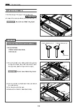
(1) Removal of Sub-Frame .........................................120
(2) Removal of Drum Gear and Driving Assy...........121
n
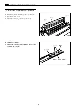
Paper Ejection Section ..............................................122
(1) Removal of Paper Stripper Finger /
Sub Paper Stripper Finger...................................122
(2) Removal of Paper Ejection Fan Unit ...................123
(3) Removal of Paper Ejection Belt ...........................124
(4) Removal of Paper Ejection Jam Sensor ..............124
(5) Removal of Top Blow Fan Unit ............................125
(6) Removal of Fan .....................................................125
(7) Removal of Pressure Adjustment Unit................126
(8) Removal of Press Motor........................................126
m
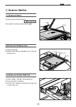
Drum Section .............................................................127
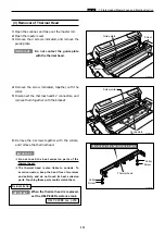
(1) Removal of Screen ...............................................127
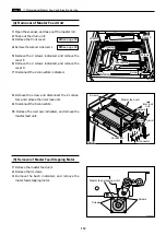
(2) Removal of Master Clamp....................................128
(3) Removal of Base Unit ...........................................128
(4) Removal of Outer Frame (Right) Unit.................129
(5) Removal of Outer Frame (Left) Assy...................130
(6) Removal of Inner Frame ......................................131
(7) Removal of Ink Pump ...........................................132
(8) Removal of Ink Pump Motor ................................132
(9) Removal of Ink Detection PCB Unit....................133
(10) Removal of Ink Roller Up/Down Motor .............133
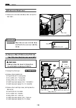
•
Always remove the power cord plug from the outlet before
starting work.
•
In principle, do not operate this machine with parts removed.
•
When assembling:
•
Unless specified otherwise, perform the disassembly procedure in
reverse.
•
Make sure that screw types (radius, length) and locations are correct.
•
Be sure to use rosette washers when they are specified.
(Rosette washers are used with installation screws to prevent static
electricity.)
•
To ensure electrical current, a rosette washer is used with the
installation screw on the ground wire. Be sure to use the rosette
washer during assembly.
•
Cautions Regarding Disassembly and Assembly
CAUTION
Содержание DP-S Series
Страница 1: ......
Страница 9: ......
Страница 11: ......
Страница 16: ...x Dimensions chap 1 15 R8S01001 xDimensions 622 1360 510 228 1080 710 980 688 370 mm...
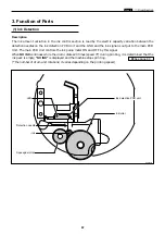
Страница 22: ...v Part Names and Their Functions chap 1 21 44000A1e 2A 2B 2C R8S01006a 2Detailed drawing...
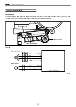
Страница 33: ...32 z Scanner Section chap 2 Circuit R8S02E03e...
Страница 53: ...52 x Platemaking Master Feed Ejection Section chap 2 2 Master Attach Detach Operation R8S02037e...
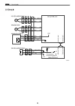
Страница 87: ...86 m Drum Section chap 2 2 Circuit R8S02E30...
Страница 171: ...170 MEMO...
Страница 193: ...192 MEMO...
Страница 195: ...194 z Help mode List chap 7 z HELP Mode List...
Страница 243: ...242 c HELP Mode Function and Operation Procedures chap 7...
Страница 270: ...269 c HELP Mode Function and Operation Procedures chap 7...
Страница 281: ...280 MEMO...
Страница 293: ...292 z Electrical Parts Layout and Their Functions chap 9 MEMO...
Страница 294: ...293 x Overall Wiring Layout chap 9 x Overall Wiring Layout Overall Wiring Layout 1 Main PCB 1 2...
Страница 295: ...309 294 x Overall Wiring Layout chap 9 Overall Wiring Layout 1 Main PCB 2 2...
Страница 296: ...310 O 295 x Overall Wiring Layout chap 9 2 Overall Wiring Layout 2 Overall Wiring Layout 2 Drive PCB 1 2...
Страница 297: ...311 296 x Overall Wiring Layout chap 9 Overall Wiring Layout 2 Drive PCB 2 2...
Страница 298: ...297 Reproduction prohibited 1st printing February 2007 Issued by DUPLO SEIKO CORPORATION PRINTED IN JAPAN...