108
x
Scanner Section
chap.3
Reinstallation
1.
Remove the document cover.
2.
Remove the scanner outer cover(Front,Rear).
3.
Remove the control panel.
4.
Remove the rear cover.
\
See page 100
\
See page 101
\
See page 99
\
See page 98
5.
Remove the screw indicated, and remove the
stopper.
6.
Remove the screw indicated, and remove the angle.
7.
Press the
scanner switch
to slide the scanner
unit.
8.
Remove 6 screws and then remove the scanner
unit by sliding it to the paper ejection side.
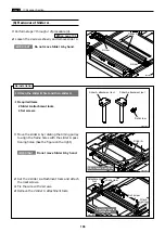
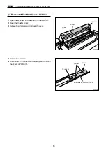
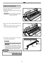
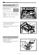
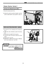
(8) Removal of Scanner unit
Notch
R8S03032
R8S03031
Rail
Slide stopper
Screws
Screws
Rail
Notch
Screw
hole
Scanner
unit
Screw hole
Screw hole
Screw hole
Screw
hole
R8S03031a
Screw
Screw
Scanner switch
Angle
Stopper
Stopper
Angle
Do not place the scanner unit
directly on the floor.
IMPORTANT :
When closing the scanner unit, the
rail holes align with the frame holes.
NOTE :
1.
Place the scanner unit on the notches from the
paper ejection side.
2.
Close the scanner unit.
3.
Slide the scanner unit and attach the 6 screws.
4.
Set the stopper and attach the screw.
5.
Set the angle and attach the screw.
6.
Close the scanner unit.
Screw
holes
Screw
hole
Screw
holes
Содержание DP-S Series
Страница 1: ......
Страница 9: ......
Страница 11: ......
Страница 16: ...x Dimensions chap 1 15 R8S01001 xDimensions 622 1360 510 228 1080 710 980 688 370 mm...
Страница 22: ...v Part Names and Their Functions chap 1 21 44000A1e 2A 2B 2C R8S01006a 2Detailed drawing...
Страница 33: ...32 z Scanner Section chap 2 Circuit R8S02E03e...
Страница 53: ...52 x Platemaking Master Feed Ejection Section chap 2 2 Master Attach Detach Operation R8S02037e...
Страница 87: ...86 m Drum Section chap 2 2 Circuit R8S02E30...
Страница 171: ...170 MEMO...
Страница 193: ...192 MEMO...
Страница 195: ...194 z Help mode List chap 7 z HELP Mode List...
Страница 243: ...242 c HELP Mode Function and Operation Procedures chap 7...
Страница 270: ...269 c HELP Mode Function and Operation Procedures chap 7...
Страница 281: ...280 MEMO...
Страница 293: ...292 z Electrical Parts Layout and Their Functions chap 9 MEMO...
Страница 294: ...293 x Overall Wiring Layout chap 9 x Overall Wiring Layout Overall Wiring Layout 1 Main PCB 1 2...
Страница 295: ...309 294 x Overall Wiring Layout chap 9 Overall Wiring Layout 1 Main PCB 2 2...
Страница 296: ...310 O 295 x Overall Wiring Layout chap 9 2 Overall Wiring Layout 2 Overall Wiring Layout 2 Drive PCB 1 2...
Страница 297: ...311 296 x Overall Wiring Layout chap 9 Overall Wiring Layout 2 Drive PCB 2 2...
Страница 298: ...297 Reproduction prohibited 1st printing February 2007 Issued by DUPLO SEIKO CORPORATION PRINTED IN JAPAN...


