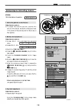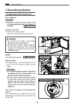
162
,
Electrical system
chap.4
Adjustment procedure
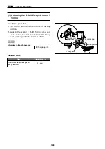
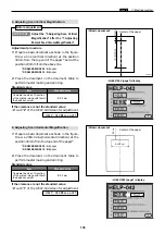
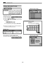
1) Perform platemaking and printing of the online test pattern. Adjust with the HELP - 047 so that
the basic line is positioned
± 1mm
from the top end of the paper.
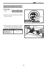
(4) Adjusting the Master making Start Position
¡
Adjust the
master making start position
when in online after the
printing position sensor
and
master attach position edge
are adjusted.
\
See page 151
\
See page 149
¡
Adjust the
master making start position
with the scanner in use after the
printing position sensor
,
master attach position edge
and
top end reading start position
are adjusted.
\
See page 161
\
See page 151
\
See page 149
IMPORTANT :
Adjustment procedure
1.
Set the printing position (vertical direction) to the
standard.
2.
Draw a line at the position 30mm from the top
end of the document and prepare a basic document
as shown in the figure.
3.
Compare the processed image with the basic
document.
Check the difference of the lines in the horizontal
direction.
4.
Adjust with the HELP - 046 (
5. M-MARK VERTICAL
START POS
) so that
L1 - L2
± 1mm
.
Adjusting direction
¡
L1 < L2 :
The value is decreased.
¡
L1 > L2 :
The value is increased.
HELP - 046
\
see p.254
¡
Basic document
HELP - 047
\
see p.255
Mark this corner with each other
Document
basic line
L2
L1
Document
Printing paper
Print ejection
direction
Basic line of the
printed sample
23S0316
23S0317
Draw a line at the position 30mm
from the top end of the document
Before adjustment
IMPORTANT :
Before adjustment
1. When the Scanner Is in Use
2. When in Online
Содержание DP-S Series
Страница 1: ......
Страница 9: ......
Страница 11: ......
Страница 16: ...x Dimensions chap 1 15 R8S01001 xDimensions 622 1360 510 228 1080 710 980 688 370 mm...
Страница 22: ...v Part Names and Their Functions chap 1 21 44000A1e 2A 2B 2C R8S01006a 2Detailed drawing...
Страница 33: ...32 z Scanner Section chap 2 Circuit R8S02E03e...
Страница 53: ...52 x Platemaking Master Feed Ejection Section chap 2 2 Master Attach Detach Operation R8S02037e...
Страница 87: ...86 m Drum Section chap 2 2 Circuit R8S02E30...
Страница 171: ...170 MEMO...
Страница 193: ...192 MEMO...
Страница 195: ...194 z Help mode List chap 7 z HELP Mode List...
Страница 243: ...242 c HELP Mode Function and Operation Procedures chap 7...
Страница 270: ...269 c HELP Mode Function and Operation Procedures chap 7...
Страница 281: ...280 MEMO...
Страница 293: ...292 z Electrical Parts Layout and Their Functions chap 9 MEMO...
Страница 294: ...293 x Overall Wiring Layout chap 9 x Overall Wiring Layout Overall Wiring Layout 1 Main PCB 1 2...
Страница 295: ...309 294 x Overall Wiring Layout chap 9 Overall Wiring Layout 1 Main PCB 2 2...
Страница 296: ...310 O 295 x Overall Wiring Layout chap 9 2 Overall Wiring Layout 2 Overall Wiring Layout 2 Drive PCB 1 2...
Страница 297: ...311 296 x Overall Wiring Layout chap 9 Overall Wiring Layout 2 Drive PCB 2 2...
Страница 298: ...297 Reproduction prohibited 1st printing February 2007 Issued by DUPLO SEIKO CORPORATION PRINTED IN JAPAN...

