


Chapter 3
26
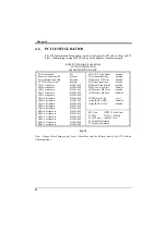
3.11
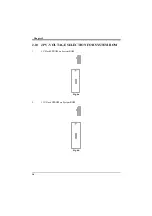
J13 - AT POWER CONNECTOR
J13 is a 12 pin male connector. Plug the power connector of AT power supply onto
the connector.
Pin
Description
Pin
Description
1
Power Good (Orange)
7
Ground (Black)
2
+5 VDC (Red)
8
Ground (Black)
3
+12 VDC (Yellow)
9
-5 VDC (White)
4
-12 VDC (Blue)
10
+5 VDC (Red)
5
Ground (Black)
11
+5 VDC (Red)
6
Ground (Black)
12
+5 VDC (Red)
Table 9: AT Power Connector
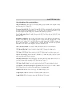
3.12
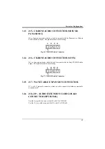
J14 - ATX POWER CONNECTOR
J14 is a 2x10 pin male connector. Plug the power connector of the ATX power
supply onto the connector.
Fig. 15 ATX Power Connector
Содержание PAM-0067V
Страница 2: ......
Страница 8: ...Chapter 1 2 Fig 1 Key Components of the Mainboard ...
Страница 16: ...Chapter 2 10 2 3 GRAPHICAL DESCRIPTION OF JUMPER SETTINGS Fig 3 Jumper Location of the mainboard ...
Страница 28: ...Chapter 3 22 Fig 9a Optional GOI 660 Extension Card Fig 9b Optional GOI 603 Extension Card ...
Страница 36: ...Chapter 3 30 ...
Страница 56: ...Chapter 4 50 ...
Страница 64: ...Chapter 5 58 ...
Страница 73: ...Quick Guide 67 ...
Страница 75: ...Quick Guide 69 ...
Страница 76: ...Appendix A 70 ...
Страница 77: ...Quick Guide 71 ...
Страница 78: ...Appendix A 72 ...
Страница 79: ...Quick Guide 73 ...
Страница 80: ...Appendix A 74 ...
Страница 81: ...Quick Guide 75 ...