Connector Configuration
25
3.8
J9 - IrDA/FAST IR CONNECTOR
J9 is a five pin connector, which use the UART2 as interface for IrDA. You must
also configure the setting through “UART2 Mode” is Integrated Peripheral Setup to
select whether UART2 is used for COM2 or HPSIR/SKSIR. The pin definition is as
following:
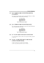
Fig. 14 IrDA/Fast IR Connector
3.9
J10, J11 - PRIMARY/SECONDARY IDE
CONNECTOR
These connectors support the provided IDE hard disk ribbon cable. After
connecting the single end to the board, connect the two plugs on the other end to
your hard disk.
3.10
J12 - FLOPPY DRIVE CONNECTOR
This connector supports the floppy drive ribbon cable. After connecting the single
end to the board, connect the two plugs on the other end to the floppy drive.
Содержание PAM-0067V
Страница 2: ......
Страница 8: ...Chapter 1 2 Fig 1 Key Components of the Mainboard ...
Страница 16: ...Chapter 2 10 2 3 GRAPHICAL DESCRIPTION OF JUMPER SETTINGS Fig 3 Jumper Location of the mainboard ...
Страница 28: ...Chapter 3 22 Fig 9a Optional GOI 660 Extension Card Fig 9b Optional GOI 603 Extension Card ...
Страница 36: ...Chapter 3 30 ...
Страница 56: ...Chapter 4 50 ...
Страница 64: ...Chapter 5 58 ...
Страница 73: ...Quick Guide 67 ...
Страница 75: ...Quick Guide 69 ...
Страница 76: ...Appendix A 70 ...
Страница 77: ...Quick Guide 71 ...
Страница 78: ...Appendix A 72 ...
Страница 79: ...Quick Guide 73 ...
Страница 80: ...Appendix A 74 ...
Страница 81: ...Quick Guide 75 ...

