


Connector Configuration
23
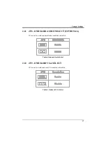
3.1
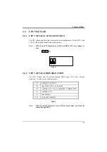
J1 – MULTIPLE FUNCTION JUMPER
J1 is a front panel multi-function jumper include speaker, reset, keylock, harddisk,
LED, ATX power switch, ACPI (suspend) LED and power button (suspend switch).
The pin definition is as following figure.
Fig. 10 Multiple Function Jumper
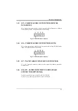
3.2
J2 – CPU FAN CONNECTION
J2 is a three pin connector, which is used to connect with the CPU FAN power
cable.
Fig. 11 CPU Fan Connector
3.3
J3 – FEATURE CONNECTOR
This connector is the feature connector for VGA controller.
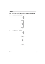
3.4
J4 – TV-OUT CONNECTOR
This connector is the extension connector for TV-OUT support, use the cable to
connect on board J4 pin1,2 to J4 pin1,2 of GOI-603 extension card.
1 2 3
Содержание PAM-0067V
Страница 2: ......
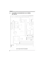
Страница 8: ...Chapter 1 2 Fig 1 Key Components of the Mainboard ...
Страница 16: ...Chapter 2 10 2 3 GRAPHICAL DESCRIPTION OF JUMPER SETTINGS Fig 3 Jumper Location of the mainboard ...
Страница 28: ...Chapter 3 22 Fig 9a Optional GOI 660 Extension Card Fig 9b Optional GOI 603 Extension Card ...
Страница 36: ...Chapter 3 30 ...
Страница 56: ...Chapter 4 50 ...
Страница 64: ...Chapter 5 58 ...
Страница 73: ...Quick Guide 67 ...
Страница 75: ...Quick Guide 69 ...
Страница 76: ...Appendix A 70 ...
Страница 77: ...Quick Guide 71 ...
Страница 78: ...Appendix A 72 ...
Страница 79: ...Quick Guide 73 ...
Страница 80: ...Appendix A 74 ...
Страница 81: ...Quick Guide 75 ...