


Drivecon Inc. reserves the right to alter or amend the above information without notice.
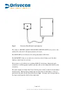
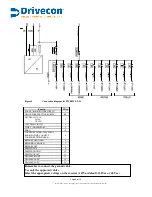
Figure 5
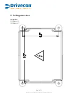
Connection diagram for PWRSII 6-2-13
Functio
Wire
PHASE (RADIO POWER SUPPLY)
1
GROUND (PROTECTIVE EARTH)
PE
2
NEUTRAL 115VAC
48VAC
230VAC
SELETION-1
16
SELETION-2
17
LATCHING CIRCUIT
4
START (MOMENTARY)
3
HORN
12
5
CONTROL POWER (IF SAME AS
RADIO POWER, CONNECT
TOGETHER WITH WIRE #1)
BRIDGE FORDWARD
6
BRIDGE BACKWARD
7
BRIDGE FAST
8
HOISTING UP
9
HOISTING DOWN
10
HOISTING FAST
11
TROLLEY RIGHT
13
TROLLEY LEFT
14
TROLLEY FAST
15
CURRENT LOOP
18
CURRENT LOOP
19
Remember to connect the ground cable.
Use only the approved cables.
Select the appropriate voltage on the receiver (115Vac default, 230Vac or 48 Vac).
Page 7 of 18


