Drivecon PWR II Series Скачать руководство пользователя страница 15


Drivecon Inc. reserves the right to alter or amend the above information without notice. 


6   HOW TO ACCESS THE HOIST CONDITION MONITORING UNIT 

THROUGH PWRSII 6-2-13 RADIO SERVICE MODE 

(IFAPPLICABLE

).  

6.1 General Description of Service Mode  

  
For   PWRSII   6-2-13   systems,   there   is   a   special   “Service   Mode”   of   operation   for  
maintenance and set up of the Hoist Condition Monitoring Unit via radio.  
  

This unit is connected to the receiver PWRS 6-2-13 by a serial data communication  
CL20mA.  
  
When in Service mode, the transmitter PWRS 6-2-13 is able to act as a data console for  
the Hoist Condition Monitoring Unit, sending commands and receiving information,  

using the radio link and the appropriate software in the transmitter PWRS 6-2-13 and in  
the receiver PWRS 6-2-13.  
  
During the Service Mode of operation, due to the amount of data being sent in the  
reverse link, the amount of frames per second in reverse mode is increased such that the  

feedback in the display is fast enough. The movements of the crane in this mode of  
operation   are   inhibited,   this   is,   there   are   no   movement   orders   being   sent   by   the  
transmitter or acknowledged by the receiver. The Stop relays are activated.  
  

PLEASE NOTE:  

 It could be too slow to enter in service mode by the receiver if the transmitter and the  
receiver are in different channels. Whenever possible, avoid the scanning of radio  
channels.  
  

6.2 

  Entering the Service mode.


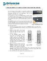
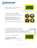
To access the Hoist Condition Monitoring Unit mode follow  
the sequence:  


1.   Install a charged battery in the transmitter.  
2.   Move close to the receiver.  
3.   Turn on the key-switch.  
4.   Push down STOP pushbutton (If it was in  up position.   
5.   Pull up STOP push button.  
6.   Press   Pushbutton UP in second step, and then START.                              
   The system enters in Service Mode. See figure 9.  

Figure 9  Entering the Service mode.


Page 13 of18


Содержание PWR II Series

Страница 1: ...Drivecon Inc reserves the right to alter or amend the above information without notice Ver 1 0 USER S MANUAL PWR Series II RADIO REMOTE CONTROL SYSTEMS 0341...

Страница 2: ...ctual Load 14 6 5 Resetting the Tared Load 14 6 6 Exiting Service Mode 15 6 7 Messages originated in the receiver 15 7 MAINTENANCE 16 7 1 Precautions 16 7 2 Preventive Maintenance 16 7 3 Locating Brea...

Страница 3: ...systems are PWRSII Systems In EU countries In North America Frequency band 869 7 to 870MHz 902 to 928MHz Baud rate 7200 bps Channel separation 12 5 KHz 25 KHz Channel Occupation 7 2 KHz Modulation FM...

Страница 4: ...afety regulations are followed Make sure that this manual is permanently available to the operator and maintenance personnel Keep the transmitter out of reach of unauthorised personnel Remove the tran...

Страница 5: ...ould light up indicating that recharging is in process Complete recharging takes approximately 12 hours After charging process is finished the green LED is turned OFF The batteries may remain in the c...

Страница 6: ...Check the power supply voltage and turn off the main switch Find a suitable location for the receiver away from any intense radio electric disturbance sources and install the receiver using the 4 elas...

Страница 7: ...ich is activated when any of the other function control relay are activated The receiver is a class II device according EN50178 containing a functional earth connection A in Europe green yellow ground...

Страница 8: ...30VAC LATCHING CIRCUIT 4 START MOMENTARY 3 HORN 12 5 CONTROL POWER IF SAME AS RADIO POWER CONNECT TOGETHER WITH WIRE 1 BRIDGE FORDWARD 6 BRIDGE BACKWARD 7 BRIDGE FAST 8 HOISTING UP 9 HOISTING DOWN 10...

Страница 9: ...17 LATCHING CIRCUIT 4 START MOMENTARY 3 HORN 12 5 CONTROL POWER IF SAME AS RADIO POWER CONNECT TOGETHER WITH WIRE 1 BRIDGE FORDWARD 6 BRIDGE BACKWARD 7 BRIDGE FAST 8 HOISTING UP 9 HOISTING DOWN 10 HO...

Страница 10: ...EDs should now light up POWER ON indicating that the power supply is correct HARDOK ON indicating the absence of defects on the board SIGNAL OFF if all radio channels in the band are free Flashing ON...

Страница 11: ...he WORKING mode The following LEDs will light up on the receiver POWER HARDOK ON indicating the absence of defects on the board SIGNAL Flashing ON indicate that it is receiving a RF signal at the work...

Страница 12: ...to the SCANNING mode Reconnect the power supply to the motors move to the usual work position and check to see if all the motions and the STOP button are functioning correctly 3 4 Spurious Disturbanc...

Страница 13: ...nsmitting From now on if any of the transmitter s command buttons are pressed the corresponding motion will be activated To be able to start up the transmitter all the command pushbuttons must be in t...

Страница 14: ...With the replacement transmitter off remove its EEPROM module as described above and insert the EEPROM module containing system information old transmitter or receiver module 2 Insert a charged batter...

Страница 15: ...ue to the amount of data being sent in the reverse link the amount of frames per second in reverse mode is increased such that the feedback in the display is fast enough The movements of the crane in...

Страница 16: ...tton that simulate the Esc Key Left button _ ENTER Button that simulate the Enter Key Right button _ Figure 11 Pushbutton as a Key board for Hoist Condition Monitoring Unit 6 4 Switching from Tared Lo...

Страница 17: ...e three possible messages that may appear apart from the messages originated by the Hoist Condition Monitoring Unit These are EXITING SERVICE MODE This message is originated when the Hoist Condition M...

Страница 18: ...if soldering welding work is going to be carried out on the crane 7 2 Preventive maintenance A few simple checks can show certain defects which can later be the cause of subsequent break downs and wh...

Страница 19: ...more Radio Systems sharing the own channel POWER Green Power supply OK Power supply NOTOK Green Board OK Failure in board HARD OK Slow Failure in board Fast EEPROM error ID Green ID Code OK Not recogn...

Страница 20: ...Drivecon Inc reserves the right to alter or amend the above information without notice 8 Drilling pattern sheet NO SCALE 255 5mm 10 169 5mm 6 7 Page 18 of 18...

Отзывы: