


Drivecon Inc. reserves the right to alter or amend the above information without notice.
1
CONFORMITY DECLARATION…………………………………………………………1
2 SAFETY PRECAUTIONS………………………………………………………………...2
2.1 What you must do…………………………………………………………………..... 2
2.2 What you must not do………………………………………………………………. 2
3 INSTALLATION..………………………………………………………………………….3
3.1 BC60K battery charger………………………………………………………………..3
3.2 Receiver……………………………………………………………………………….4
3.3 Starting Up…………………………………………………………………………….8
3.4 Spurious Disturbance………………………………………………………………...10
4 USE…………………………………………………………………………………………11
5 PROGRAMMING OF A REPLACEMENT TRANSMITTER……………………………12
6 HOW TO ACCESS THE HOIST CONDITION MONITORING IN PWRSII 6-2-13
SYSTEM. SERVICE MODE………………………………………………………………13
6.1
General Description of Service Mode………………………………………………..13
6.2
Entering the Service Mode…………………………………………………………...13
6.3
Keys for moving within the Menus…………………………………………………..14
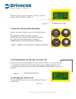
6.4
Switching from Tared Load to Actual Load………………………………………….14
6.5
Resetting the Tared Load……………………………………………………………..14
6.6
Exiting Service Mode ………………………………………………………………...15
6.7
Messages originated in the receiver…………………………………………………..15
7
MAINTENANCE…………………………………………………………………………..16
7.1
Precautions…………………………………………………………………………….16
7.2
Preventive Maintenance……………………………………………………………….16
7.3
Locating Breakdowns…………………………………………………………………17
8 DRILLING PATTERN SHEET……………………………………………………………18
I N D E X
Pg.
Figure 1
Battery charger BC60K .................................................................................3
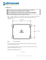
Figure 2
Receiver Box dimensions ............................................................................. 4
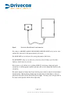
Figure 3
Receiver to Power Electric Circuit connection...............................................5
Figure 4
Connection diagram for PWRSII 6-2-11 ...................................................... 6
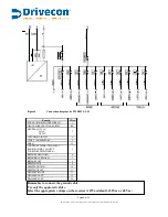
Figure 5
Connection diagram for PWRSII 6-2-13 ...................................................... 7
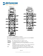
Figure 6
PWRSII 6-2-11 and PWRSII 6-2-13 transmitters ...................................... ..9
Figure 7 EEPROM REPLACEMENT……………………………………………….12
Entering the Service mode. ......................................................................... 13
Figure 8 PWRSII…………………………………………………………………... 12
LCD Display in Service Mode.................................................................... 14
Figure 9
Figure 11 Pushbutton as keyboard for Hoist Condition Monitoring Unt......................14
Figure 10
Figure 12 LCD representing Tared Load .................................................................... .14
INDEX OF FIGURES


