Service Manual
rev 5.0 with software Ind1V022
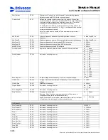
Start Current
P2.2.6
Start current. Current level, which is used in motor starting situation.
Default value equals P2.2.4 Motor nominal current.
Current Limit
P2.2.7
Defines the maximum motor current from the inverter. If the output
current exceeds the value set in parameter P2.2.7 the output frequency
is lowered until the current drops below the current limit. The rate of
lowering the frequency depends on the current overshoot.
To avoid motor overloading, set this parameter according to the rated
current of the motor (normally 1,5....2xIn). In multimotor drives nominal
currents must be summarized.
Note! The value must be limited to Drive maximum output current (1
minute value).
Min Freq S1
P2.2.8
Minimum frequency forwards. Must be higher than motor slip
frequency.
0 – Max Freq S2, Hz
Min Freq S2
P2.2.9
Minimum frequency reverse. Must be higher than motor slip frequency.
0 – Max Freq S2, Hz
Max Freq S1
P2.2.10
Maximum frequency forwards, when ESR is not active.
0 – 250 Hz
Max Freq S2
P2.2.11
Maximum frequency reverse, when ESR is not active.
0 – 250 Hz
Max ESR freq
P2.2.12
Maximum frequency when ESR activated
0 – 250 Hz
0 =
None
1 =
Travel
Drive Selection
P2.2.13
Application selection, selection None causes F60 Parameter fault.
2 =
Hoist
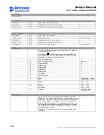
0 =
24
1 =
36
2 =
48
3 =
72
4 =
32
5 =
64
6 =
80
7 =
102
8 =
600
9 =
1000
10 =
1024
Pulse Number
P2.2.14
Not used in travelling inverter
11 =
2000
Zero Freq Volt
P2.2.15
Output voltage at zero frequency, % of motor nominal voltage.
0 – 40 %
U/f Mid Volt
P2.2.16
Voltage in the selected middle point frequency, % of motor nominal
voltage.
0 – 100 %
U/f Mid Freq
P2.2.17
Middle point frequency.
0 – 250 Hz
0 =
Off
Torque Boost
P2.2.18
Not used in travelling inverter
1 =
On
RS Voltage Drop
P2.2.19
Not used in travelling inverter
0 – 512
0 =
Brake
Stop Function
P2.2.20
Stopping mode selection
Ramping: When the drive command is switched off the motion is
stopped according to the set deceleration ramp.
Brake: When the drive command is switched off the motor current is cut
off and the motion is stopped by the mechanical brake.
1 =
Ramping
G2.3 Expert
Flux Current Kp
P2.3.1
Not used in travelling inverter
0 - 32000
Flux Current Ti
P2.3.2
Not used in travelling inverter
0 – 1000 ms
S2 Flux Control
P2.3.3
Not used in travelling inverter
0 – 100 %
Freq 0
P2.3.4
Not used in travelling inverter
0 – 100 %
Freq 1
P2.3.5
Not used in travelling inverter
0 – 100 %
Freq 2 S1
P2.3.6
Not used in travelling inverter
0 – 100 %
Freq 3 S1
P2.3.7
Not used in travelling inverter
0 – 100 %
Zero Flux Curr
P2.3.8
Not used in travelling inverter
0 – 100 %
Stray Flux Curr
P2.3.9
Not used in travelling inverter
0 – 100 %
Freq 2 S2
P2.3.10
Not used in travelling inverter
0 – 100 %
Freq 3 S2
P2.3.11
Not used in travelling inverter
0 – 100 %
30/58
Drivecon Inc. reserves the right to alter or amend the above information without notice.
Содержание D2L
Страница 59: ......


