background image

                                                             Service Manual 

                                                                 rev 5.0 with software Ind1V022


After a time delay (normally 0.3s), the delayed contact of the brake contactor opens, which disconnects the 
supply from terminal 3 and the rectifier changes to a half wave type. Half wave operation prevents heating of 
the brake coil and is enough to keep the brake open. 
 
To close the brake, the brake contactor disconnects the supply to terminals 1 and 2. The released brake 
contactor also opens the brake coil DC-circuit, which speeds closing of the brake. The purpose of the varistor 
there is overvoltage protection for K7 contacts and the brake coil. 


25/58 

Drivecon Inc. reserves the right to alter or amend the above information without notice.


Содержание D2L

Страница 1: ...s manual is for inverter rev 5 0 with software Ind1V022 XT Series D2L Service Manual for D2L Hoisting Inverter 820 Lakeside Drive Gurnee IL 60031 9165 Tel 1 800 374 8266 Fax 847 855 9650 www drivecon...

Страница 2: ...r sensor bearing 40 2 3 6 Du dt filters 13 7 1 2 Settings for pulse wheel speed sensor or encoder 24 ppr 40 2 4 Signal cabling 13 2 4 1 Shielded signal cable 13 7 2 Functional test run for SSU 41 2 4...

Страница 3: ...the device when it is connected to the main supply Do not touch the components on the circuit boards Static voltage discharge may cause damage or destroy the IC circuits Check all ventilation holes a...

Страница 4: ...0 200 Braking torque 150 Protections Stall prevention During acceleration and constant speed Motor overload protection Thermistor based temperature measurement Overload protection Fault is detected if...

Страница 5: ...for signals with main control and electronics voltage levels Brake control D2L include the brake contactor for disk brakes D2L also includes it s own DC rectifier Electrical Braking D2L includes the b...

Страница 6: ...ffer amplifier for speed sensor B5 Speed sensor B6 Thermal sensor for motor protection Overload protection device Control devices switches pushbuttons etc Limit switches Example Layout of D2L030 Z1 K7...

Страница 7: ...es and the mechanical brake stops the motion Independent speed supervision unit SSU The speed measurement and supervision can be done either with encoder bearing sensor or proximity switch The measure...

Страница 8: ...s standstill 0 position step one switch S1 or S2 is the minimum speed command step two EP hold command means hold speed step three switch AP means acceleration up to the maximum speed if desired when...

Страница 9: ...ide D2L This connection can also be used to control 2 phase disk brakes or a separate KA372B brake control unit 1 8 EMC The shortening EMC stands for the Electro Magnetic Compatibility According to th...

Страница 10: ...Service Manual rev 5 0 with software Ind1V022 2000 for the second environment 10 58 Drivecon Inc reserves the right to alter or amend the above information without notice...

Страница 11: ...2 3 3 Cable selection Cabling for inverter can be done using normal crane cables All the cables must be dimensioned according to local regulations Ambient temperature cabling method size of bunches e...

Страница 12: ...re must be fuses or motor circuit breakers MCCBs installed at the mains end of the supply cable Dimensioning of the fuses or MCCBs depends on the cable used and on the type of primary fuses or MCCBs I...

Страница 13: ...25 7 52306555 022 045 ULC 923 927 190 135 260 12 52306556 055 ULC 942 1044 240 175 310 22 52306557 Du dt filter should be as near D2L as possible Note All control cables must be placed as far from the...

Страница 14: ...uction parts of the cubicle must be electrically connected to each other using largest possible surface area Paint to paint connection must not be used 2 5 2 Cable connections Control cables and power...

Страница 15: ...F1e000 10 15 6 13 D2V005NF1e000 13 20 6 13 D2V007NF1e000 18 27 10 22 D2V011NF1e000 24 36 10 22 D2V015NF1e000 32 48 20 44 D2V018NF1e000 42 63 20 44 D2V022NF1e000 48 72 20 44 D2V030NF1e000 60 90 37 82 D...

Страница 16: ...for supply cables motor cables and braking resistor cables PSU also includes a D connector for CSU connection Main supply voltage terminals L1 Mains L1 L2 Mains L2 L3 Mains L3 PE Protective earth DC b...

Страница 17: ...s blinking 0 5Hz blinking 0 5Hz Everything is OK IEC Application Scheduler is running and Application is running blinking 0 25Hz blinking 0 5Hz IEC Application Scheduler is running and Application is...

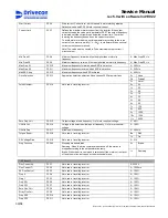
Страница 18: ...0Vac 50 60Hz 16 OK Digital input 42 240Vac 50 60Hz OK signal OK input is connected straight to the ASIC Inverter is ready to operate when OK signal is active 1 17 COM Common for 42 240Vac 50 60Hz 18 C...

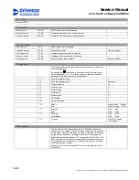
Страница 19: ...ID4 42 240Vac 50 60Hz 5 DID5 42 240Vac 50 60Hz 6 COM Common for DID1 DID5 7 ROD1 8 ROD1 Relay output 250V 8A normal open For fan of braking resistor unit The threshold voltage for digital inputs DID1...

Страница 20: ...234 1 B Blue not connected not connected 3 4 7 6 1 2 OUT 24V 0V 55 51 56 X1 24V EA 0V INVERTER WHITE BLACK 24V A 0V RED 52 EA BROWN GREEN WHITE Critical damage if The supply voltage is over 28V or a s...

Страница 21: ...EB 52 EA G yellow A green B white B terminal box D2L X1 In standard encoders there are also zero outputs Z Z which should be left disconnected If the encoder does not have negative channels A and B EA...

Страница 22: ...the table below Signal name Sensor Cable Colour marking Terminal number 24V Red Brown Brown KAE234 6 Honeywell 3GT101DC 5 12 35 29 PULSE Green Green Black KAE234 1 0V Black White Blue KAE234 2 Red Gr...

Страница 23: ...quires tooth movement past the sensor A motionless tooth can not generate a pulse 3 3 4 Buffer amplifier KAE234 The speed sensor proximity switch or sensor bearing is connected to D2L via KAE234 buffe...

Страница 24: ...coil DC circuit which speeds closing of the brake The purpose of the varistor there is overvoltage protection for K7 contacts and the brake coil 3 4 2 ESD141 Brake control unit ESD141 is a line voltag...

Страница 25: ...events heating of the brake coil and is enough to keep the brake open To close the brake the brake contactor disconnects the supply to terminals 1 and 2 The released brake contactor also opens the bra...

Страница 26: ...ning READY Power is on In case of a trip the symbol will not light up ALARM Drive is running outside of certain limit FAULT Fault is on I O term I O terminals are the selected control place Keypad Key...

Страница 27: ...ng G1 V19 READY STOP G5 Panel Control B1 R2 READY STOP M6 System Menu S1 S9 READY STOP M7 Active Faults F0 READY STOP M8 Fault History H1 Hxx READY STOP G2 2 Motor Parameters P1 P20 READY STOP P2 2 1...

Страница 28: ...number 03L50700 Parameters can be restored from Default parameters with parameter B 4 1 1 Load Default Par Enter press Enter After restoring always check the motor parameters Parameters in use can be...

Страница 29: ...g 0 250 Hz Accel Time 1 P2 1 10 Acceleration ramp is defined from zero to motor nominal frequency P2 2 2 Shorter values than the factory setting must not be used 1 300 s Decel Time 1 P2 1 11 Decelerat...

Страница 30: ...0 7 102 8 600 9 1000 10 1024 Pulse Number P2 2 14 Not used in travelling inverter 11 2000 Zero Freq Volt P2 2 15 Output voltage at zero frequency of motor nominal voltage 0 40 U f Mid Volt P2 2 16 Vol...

Страница 31: ...s to Active Parameters from the control unit memory User Parameters are the parameters which have been saved after start up G4 1 4 Factory Default Save Default Par Accel Comp TC P2 3 17 Defines the ou...

Страница 32: ...t sink C Motor Power V4 14 Calculated actual power of nominal power of unit Motor Voltage V4 15 Calculated motor voltage V Motor Torque V4 16 Calculated motor torque motor nominal torque positive when...

Страница 33: ...ominal voltage of the power unit Software version I6 7 3 Control unit software version Firmware interf I6 7 4 Application interface version of the software 4 16 S6 7 5 Expanders A E6 7 5 1 Type of exp...

Страница 34: ...days d T 2 Counted operation hours hh mm ss T 3 Output frequency Hz T 4 Motor current A T 5 Motor voltage V T 6 Motor power T 7 Motor torque T 8 DC voltage V T 9 Unit temperature C T 10 Ready Run 0 N...

Страница 35: ...x ESR Freq 120 P 2 2 12 Max ESR Freq 120 P 2 2 13 Drive Selection Hoist P 2 2 13 Drive Selection Hoist P 2 2 13 Drive Selection Hoist P 2 2 13 Drive Selection Hoist P 2 2 14 Pulse Number 32 P 2 2 14 P...

Страница 36: ...0 Max Freq S1 100 P 2 2 11 Max Freq S2 120 120 P 2 2 12 Max ESR Freq P 2 2 13 Drive Selection Hoist P 2 2 13 Drive Selection Hoist P 2 2 13 Pulse Number 63 P 2 2 14 P 2 2 14 Pulse Number 80 P 2 2 15 P...

Страница 37: ...ulse Number 32 P 2 2 14 Pulse Number 64 P 2 2 15 Zero Freq Volt 0 P 2 2 15 Zero Freq Volt 0 P 2 2 15 Zero Freq Volt 0 P 2 2 15 Zero Freq Volt 0 P 2 2 16 U f Mid Volt 8 P 2 2 16 U f Mid Volt 7 P 2 2 16...

Страница 38: ...q Volt 0 U f Mid Volt 8 U f Mid Volt 8 P 2 2 16 U f Mid Volt 8 U f Mid Freq 0 P 2 2 17 U f Mid Freq 0 U f Mid Freq 0 P 2 2 18 Torque Boost On P 2 2 18 Torque Boost On P 2 2 18 Torque Boost On Rs Volta...

Страница 39: ...ed detection level Range of detection level is the same for both normal and ESR Extended Speed range use Fine adjustment for normal use is done by rotary switch S1 and switch S2 1 Fine adjustment for...

Страница 40: ...itch S2 2 OFF OFF OFF Switch S2 3 OFF OFF OFF Switch S2 4 ON ON ON Rotary switch S3 1 A D 1 2 3 4 ON OFF S1 S2 S3 7 1 2 Settings for pulse wheel speed sensor or encoder 24 ppr The table below indicate...

Страница 41: ...76 1625 6502 15217 52013 951 3251 1902 7 514 1755 1027 3511 2055 7022 16439 56174 8 555 1896 1109 3793 2218 7585 17744 60681 599 2048 1198 4096 2395 A 647 2210 1296 4420 2587 8840 20696 70722 B 698 23...

Страница 42: ...uitable maximum overspeed detection level is 2400Hz 25 3000Hz S2 2 OFF and S2 3 OFF are according to normal speed settings Correct switch settings are S2 4 ON and S3 4 Encoder with 600 ppr or over nee...

Страница 43: ...tions for motor thermistors brake wear and speed sensor circuits Disconnect motor U V W and brake cables to prevent damage of inverter Measure isolation resistance of brake coil and motor windings eac...

Страница 44: ...p again and stop Check limit switch functions drive up slowly and check the slowdown and stop limit switch operations Re check using full speed Repeat the same check for down direction If the optional...

Страница 45: ...Service Manual rev 5 0 with software Ind1V022 45 58 Drivecon Inc reserves the right to alter or amend the above information without notice...

Страница 46: ...he inverter components Always if any power component inside the inverter is damaged it is also recommended to change the component that controls the damaged component In the smallest models replacing...

Страница 47: ...911Vdc Reset has an additional 5s time delay Check F 3 Earth fault Current measurement has sensed unbalance in motor phase currents Supervision level is 5 of inverter nominal current Reset has an addi...

Страница 48: ...F 32 Fan cooling fault Cooling fan of the frequency converter do not work when ON command has been given If the fault comes again contact authorized service F 35 Application fault Run time exception...

Страница 49: ...Watchdog SSU internal fault Reset switch power off and restart after the lamps of display are off Check F 66 SSU Overspeed Limit SSU overspeed limit has been set over 140 of maximum frequency Check F...

Страница 50: ...means that there has been 12 pieces overcurrent faults When counter value is blinking then you can monitor fault counter values by pressing up and down arrows xx 01 xx 02 xx 03 xx 07 xx 09 xx 10 xx 1...

Страница 51: ...vice Manual rev 5 0 with software Ind1V022 F60 F64 F65 F71 F72 V4 5 2 Total Faults Total number of all faults 51 58 Drivecon Inc reserves the right to alter or amend the above information without noti...

Страница 52: ...heck motor temperature model parameters A 50 Reference value alarm Analog input signal is out of selected range 1 9V or 2 10V control cable is broken signal source has failed Check reference cable ref...

Страница 53: ...UMBER DECELERATION TIME S CONTROL METHOD MIN SPEED Hz EP2 MAX SPEED Hz EP3 MS MOTOR INFORMATION TYPE CODE NOMINAL VOLTAGE S SERIALNUMBER NOMINAL CURRENT S U F CURVE Travelling inverter NOMINAL FREQUEN...

Страница 54: ...e heat sink of the inverter Prevent the dust to spread inside cubicles Lock the fans before blowing compressed air Check that there are no abnormal noises coming from the cooling fans Tighten all scre...

Страница 55: ...52305765 EMC level 0 1 D2V037NF1N00 52305758 EMC level N S 1 D2V037NF1000 52305764 EMC level 0 1 D2V045NF1N00 52305759 EMC level N S 1 D2V045NF1000 52305763 EMC level 0 1 D2V055NF1N00 52305761 EMC lev...

Страница 56: ...15 230VAC 1 Auxliary contact LAD 8N20 52297562 1 LAD N04 52297548 CM1 Y capacitor KC 307 00 1 1 1 52298693 42VAC 1 1 1 1 1 1 1 1 1 1 Z1 Ferrite RU2100 30 7 52299351 1 1 1 Emission level N 1 1 1 RH1752...

Страница 57: ...ection with encoder 24 ppr 55 24V 51 EA 54 EB INVERTER blue V 0V red 56 0V 53 EB 52 EA G yellow A terminal box D2L X1 55 24V 51 EA 54 EB INVERTER black blue V A 0V red 56 0V 53 EB 52 EA G yellow A gre...

Страница 58: ...es the right to alter or amend the above information without notice Standard connection with proximity switch Honeywell Colour if cable has been lengthened 55 24V 51 EA 54 EB INVERTER black V 0V red 5...

Страница 59: ......

Отзывы: