


28
OM-HY/6G(CE)
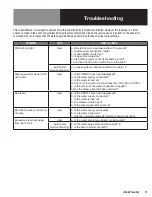
Service Procedures
To Test: With power ON, turn on the power switch to one cavity. The fill solenoid for that steam generator should energize
allowing water to enter the steam generator. When READY light is ON, spray valve solenoid should energize and water should
enter the drain box.
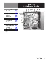
G. Water Inlet Valve Coil
If a solenoid coil on the water inlet valve is defective, replace the entire valve in accordance with Section F.
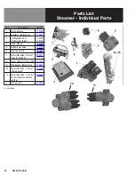
H. Drain Box Spray Nozzle (P/N
1. Raise the stainless steel vent pipe to remove it from the drain box. Do not loosen the hose clamp around the vent pipe.
The hose clamp serves to prevent the pipe from going too far into the drain box. Secure the vent pipe in the raised
position.
2. Lift the cover of the drain box. There are no fasteners holding the cover on the drain box.
3. Tip the cover and note there is a circular hole in the middle and the spray nozzle (with a hex head) is in the center of the
hole.
4. With a socket wrench, turn the spray nozzle in the counter-clockwise direction to remove.
5. To install new nozzle, place pipe compound on the nozzle threads, insert nozzle in socket wrench and start the nozzle in
the hole. Tighten nozzle.
6. Replace cover on drain box and lower vent pipe into the drain box.
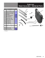
I. Steam Generator (P/N 094128 &
1. Shut off power, water and gas supply to the steamer.
2. Turn main gas valve to the OFF position.
3. Disconnect the water inlet hose, steam hose and drain hose by loosening the hose clamps and working the hose off the
respective fitting.
4. Disconnect the two boiler manifold gas lines from the gas solenoid valves.
5. Disconnect “spark” lead from igniter module and disconnect the two boiler manifold gas lines from the manifold.
Remove the gas lines from the unit.
6. Remove flame holders and/or jets if necessary.
7. Disconnect pilot line from the main gas valve.
8. Disconnect “spark” lead from igniter module and pilot burner.
9. Remove pilot burner.
10. If identification is missing from the water level probe electrical leads, identify and mark them at this time.
11. Disconnect the electrical lead from the water level probe which is being removed, and carefully remove the probe. Be
careful not to damage the ceramic material on the probe.
12. Clean the probe and the probe holder.
13. Inspect the probe and its ceramic for damage. If damaged, replace the probe.
Содержание Unified Brands Groen HyperSteam HY-6G
Страница 25: ...OM HY 6G CE 25 Electrical Schematic ...
Страница 41: ...OM HY 6G CE 41 ...
Страница 42: ...42 OM HY 6G CE ...
Страница 43: ...OM HY 6G CE 43 ...


