


OM-HY/6G(CE) 27
Service Procedures
5. Attach new drain valve to valve bracket. Pull silicone hose through drain valve and loosely install hose clamps over both
ends of the hose. Be sure silicone hose is properly aligned and does not have any kinks, bends and/or twists.
6. Position the valve over the valve mounting threaded studs and connect both ends of the hose to the drain box and steam
generator.
7. Position the spring clamps about 3 mm (1/8”) from the end of the hose.
8. Install and tighten valve mounting 10-32 cap nuts.
9. Plug valve electrical leads into the wiring harness.
To Test: Operate steamer and allow steam generator to fill. Check for leaks and observe if drain valve fully closes. Turn off
steamer and observe that drain valve opens and the steam generator drains. Install back cover.
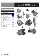
F. Water Inlet Valve - Two Way (P/N
1. Turn off power to the steamer. Turn off the water supply to the steamer. Remove the water supply hose connection on the
rear of the steamer.
2. As viewed from the rear, remove the back panel and the right panel.
3. The water inlet to the steam generators (should be supplied with treated water) has a single inlet with two individual
solenoid activated valves within a single housing. The water inlet for the drain condensate cooling water (use of regular,
untreated water is recommended) has a inlet with one solenoid activated valve. Color of wires are:
Solenoid
Wires
Top Steam Generator Fill:
Red and Black
Bottom Steam Generator Fill:
Violet and Black
Condensate Spray:
Black and White
4. Slide the hose clamps down the hose until needed for reassembly. Loosen and remove the hoses using a gentle rocking
motion.
5. From the back of the steamer, remove the two screws holding the valve assembly in place. Then lower the valve to be
replaced WITH THE WIRES STILL ATTACHED.
6. From the back of the steamer, remove the two 8-32 screws holding the valve assembly in place. Lower the valve.
7. Carefully unplug the connectors, one at a time and attach to the new valve.
8. To install a new valve, reverse the procedures and first install the four or two wires as listed in Item 3 of this Section.
Fasten the valve to the steamer with the two screws. Make sure that the valve is NOT installed upside down.
9. Re-attach the hoses to the valve. Slide the hoses all the way so that the end of the hose is flush against the face of the
valve.
IMPORTANT. Make sure that the correct steam generator hose is connected to the corresponding valve outlet. Slide the hose
clamps back into position around the end of the hose and tighten the clamps.
Slide the hose clamps so that they are within 3 mm (1/8 inch) from the end of the hose.
TOP hose:
to the TOP Steam Generator
MIDDLE hose:
to the BOTTOM Steam Generator
Hose for single valve:
to the DRAIN Box
Содержание Unified Brands Groen HyperSteam HY-6G
Страница 25: ...OM HY 6G CE 25 Electrical Schematic ...
Страница 41: ...OM HY 6G CE 41 ...
Страница 42: ...42 OM HY 6G CE ...
Страница 43: ...OM HY 6G CE 43 ...