OM/SM-AH-CE
11
b.
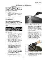
Hang a strip of pH test paper on the rim of
c.
Replace in reverse order.
the container, with about 3 cm of the strip
extending below the surface of the water.
Ensure the low water level control is correctly
c.
Measure the water treatment compound you
will be using. (One way is to add the
compound to the water from a small
measuring cup).
d.
Stir the water continuously, while you slowly
add water treatment compound, until the
water reaches a pH between 10.5 and 11.5.
Judge the pH by frequently comparing the
color of the test strip with the color chart
provided in the pH test kit.
e.
Record the exact amounts of water and
treatment compound used. These amounts
may be used again, if the same sources of
water and compound are employed to refill
the jacket in the future. However, it is
advisable to check the pH every time water
is prepared for the jacket.
f.
For optimum performance, use correctly
treated, distilled water.
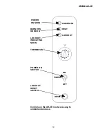
3.5 Removal of Control Panel
a.
Remove the two screws at the panel base.
b.
Remove panel
c.
Replace in reverse order.
3.6 Removal of Spark Ignition Module -
(Turn the gas and electricity mains off)
a.
Remove control panel (Paragraph 3.5).
b.
Disconnect electrical leads from spark
ignition module.
c.
Remove retaining screws securing spark
ignition module.
d.
Withdraw spark ignition module from
supporting bracket.
e.
Replace in reverse order.
3.7 Removal of Low Water Level Control
(Turn the gas and electricity mains off)
a.
Remove control panel (Paragraph 3.5)
b.
Remove low water level control from its
base by undoing the two retaining clips.
oriented when repositioned.
3.8 Removal of Gas Control Valve
- (Turn the
gas and electricity mains off)
a.
Remove control panel (Paragraph 3.5)
b.
Disconnect electrical leads from control
valve.
c.
Undo fittings on each side of control valve.
d.
Remove mounting screws from valve.
e.
Remove control valve from control cabinet.
f.
Replace in reverse order.
3.9 Removal of ON/OFF Switch and Reset
Button - (Turn the gas and electricity
mains off)
a.
Remove control panel (Paragraph 3.5).
b.
Disconnect electrical leads from the On/Off
switch or reset button.
c.
Undo and remove retaining collar which
secures the On/Off switch to the outer
surface of the control cabinet, and the reset
button to its inner surface.
d.
Withdraw the On/Off switch or the reset
button as required.
e.
Replace in reverse order.
Содержание GROEN AH-20
Страница 23: ...OM SM AH CE 23 ...
Страница 24: ...OM SM AH CE 24 Parts Lists ...


