46
ED900
02-2020
08125330
dormakaba ED900 Installation Instructions – Double egress door
Chapter 14
14.4 Full width cover option –
ED900 operator preparation and mounting plate assembly
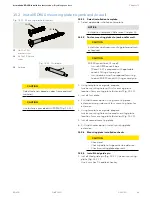
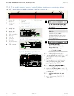
Fig. 14.4.1 ED900 active door operator
TIPS AND RECOMMENDATIONS
Reference Chapter 12 for active /inactive door
assignments.
TIPS AND RECOMMENDATIONS
Power switch on active door operator will be
replaced with single program switch
(Para. 15.8).
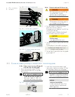
14.4.1 Remove terminal board from active door ED900.
1. Press in 3 tabs (
2
) that secure terminal board (
1
) to
ED900, lift up terminal board and swing away from
end of housing.
14.4.2 Remove ED900 115 Vac plug.
1. Swing open upper bracket (
3
).
2. Remove ED900 115 Vac plug (
5
) from power supply
circuit board socket (
6
).
14.4.3 Remove power supply circuit board.
1. Remove power supply circuit board (
4
) from its slot in
ED900.
Fig. 14.4.2 ED900 active door power switch removal
1
Terminal board
2
Tabs
3
Upper bracket
4
Power supply circuit
board
5
ED900 115 Vac plug
1
2
3
3
5
4
6
1
2
2
3
ED900 – Active door
Power switch
Spindle
Program switches

