54
ED900
02-2020
08125330
dormakaba ED900 Installation Instructions – Double egress door
Chapter 15
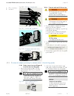
Fig. 15.7.2 Installation of ED900 on mounting plate
1
ED900 mounting
plate
2
ED900 operator
3
Guide pin
4
115 Vac plug
5
Accessory wiring
terminal connectors
Fig. 15.7.3 ED900 115Vac plug and socket
4
115 Vac plug
6
115 Vac socket
7
Power off/on switch
15.7.1 Active door – Install ED900
operator onto its mounting plate.
CAUTION
Protective film strip removal.
Insure two protective film strips
have been removed from operator
heat conductive pads (Para. 15.6).
1. Slide ED900 operator over the three
mounting plate guide pins and onto
mounting plate.
• Guide 115 Vac plug (4) into ED900
housing adjacent to socket (6).
2. Thread the eight captive ED900
M6 SHCS (7) into their mounting plate
holes using 5 mm hex T-handle.
3. Tighten the eight M5 SHCS.
15.7.2 Insert 115 Vac plug into socket.
1. Insert 115 Vac plug from mounting plate
115 Vac terminal block into ED900
socket (Fig. 15.7.2).
15.7.3 Inactive door.
1. Repeat steps in 15.7.1 and 15.7.2.
CAUTION
Full width cover option, single
program switch and cable.
As ED900 operator is lowered
onto mounting plate, route
program switch and cable into
ED900 housing.
Reference Para. 15.8.
6
115 Vac socket
7
M6 x 10 SHCS
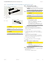
15.7 Install each ED900 operator onto its mounting plate
15.6 Remove protective film strips from each ED900 operator
1
Heat conductive
pads
Fig. 15.6.1 Operator protective film strips
15.6.1 Remove protective film strips.
1. Remove two protective film strips from
each operator's heat conductive pads.
CAUTION
Heat conductive pads.
Heat conductive pads must
remain clean once protective film
strips are removed!
1
1
4
6
7
2
5
4
6
3
3
7
7
7
7
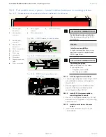
1
2
Active door
Inactive door
Fig. 15.7.1 ED900 installation
1
Single program
switch
2
Power switch


