23
ED900
02-2020
08125330
dormakaba ED900 Installation Instructions – Double egress door
Chapter 9
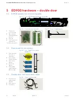
9.3 ED900 terminal board interfaces
TIPS AND RECOMMENDATIONS
Do not connect system
accessories to board until
operator has been commissioned
and learning cycle performed.
Reference Chapter 25.
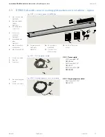
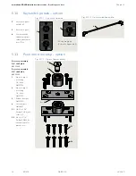
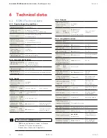
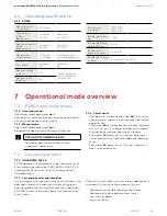
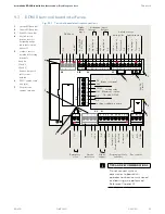
Fig. 9.3.1 Terminal board electrical connections
1
Green LED (Para. 8.4)
2
Yellow LED (Para. 8.4)
3
Red LED (Para. 8.4)
4
Key (red insert)
location in socket.
Assigned plug has
tab in same location
broken off.
5
Jumpers, factory
installed at following
terminals:
• 4 and 4a
• 15 and 3*
• 11 and 3*
*
Remove jumpers if
safety sensors
installed.
6
DCW® upgrade card
plug (n/a)
7
Fire protection
upgrade card plug
9798
99
3031
3234
33
3
3
35
1
3
6
1
4
4a
3 B A 1
57 57a
1 42 3 1 41 3
1 15 17 3 1 11 13 3
43
36
46
36
2
1G
3
+
24 V
S
ig
na
l i
np
ut
0 V
Pa
rt
ia
l O
pe
n
P
er
m
an
en
t
O
pe
n
E
xi
t
O
nl
y
A
utomatic
O
ff
N.
C.
C
O
M
Te
st ou
tp
ut
X5
X4
X3
X6
X9
X1
X7
+
24 V
X8
0 V
X10
8 - 24
A
C
/DC
+ 5%
W
et
DCW bus
Swing side
Approach side
Safety sensors
Activation inputs
Interior
Exterior
Night-
bank
input
+
24 V
S
ig
na
l i
np
ut
0 V
+
24 V
+
24 V
S
ig
na
l i
np
ut
S
ig
na
l i
np
ut
0 V
0 V
Te
st ou
tp
ut
0 V
24 V
Brake coil signal
Output
COM
N.O.
N.C.
0 V
Locking relay
Maximum current:
1A, 48 V DC/AC
Locking feedback contact
0 V
0 V
+
24 V
0 V
0 V
Signal input
N.
O
.
Smoke
detectors
Emergency
close
Night
trigger
Program, exit only
switches
Door status
24
VDC
Class II
1
2
3
4
5
6
7
5
5

