


AUTO
OFF
OFF
CLOSE
EXIT ONLY
PARTIAL OPEN
OPEN
ON
ON
I O II
Exit Only
Partial Open
Main Switch
Service display
Test cycle
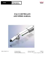
6.1 Program switch
The service display informs the facility operator that
the door system has to be serviced.
The maintenance intervals can be adjusted via PDA.
Either a time slice (monthly interval, e.g. every 6
months) and/or a certain number of opening/closing
cycles can be selected (e.g. following 80,000
opening/closing cycles).
Depending on the selected interval, the service display
blinks as follows:
Max. number of adjusted opening/closing cycles
reached:
Display illuminates permanently.
Time interval expired:
Display blinks (every 0.5 seconds).
Time and opening/closing cycle interval reached:
Display illuminates permanently for 10 seconds,
then it blinks for 10 sec.
With the aid of the PDA, a test cycle may be
performed in order to optimise the smooth
performance of the door.
Following successful commissioning and functional
testing of the unit, the documentation has to be
handed over to the facility operator and a
g has
to be made.
The program switch is installed in one of the vertical
door jambs. The following functions can be selected
using the three toggle switches:
·
·
·
6. Operation instructions
Main Switch
Switch is in position:
AUTO
OPEN
CLOSE
Switch - EXIT ONLY
(Main Switch is in AUTO position)
Switch is in position:
ON
CLOSE
Switch - PARTIAL OPEN
(Main Switch is in the AUTO position)
PARTIAL OPEN Switch is in position:
When an activation signal is received at
either Radar 1, (assuming the EXIT
ONLY switch described below is “CLOSE”),
and/or Radar 2 inputs, the door will
open. After opening, signals received
from the Presence input or the Safety
Beams, will cause the door to remain
open, open again when the door is
closes.
After all the sensors have cleared, the
hold open delay is initiated, and when it
expires, the door will close.
Continuous Open Operation
The door opens to the full opening width
and remains in this position. Manual
operation of the door is possible, with
some resistance from the operator.
The door stops immediately when the
switch is placed in this position.
In this position the exterior motion
door can only
activated from the
interior motion detector (e.g. one-way
The exterior Radar 1 is active while the
position.
When an activation signal is detected
from the interior (Radar 2), the door
opens, delays according to the hold
open time setting, then closes.
If, in addition, the Partial Open Switch is
set to the ON position, the door opens
only to the predetermined partial open
position and closes after the expiration
of the hold open delay.
The Exit Only function is switched to “CLOSE”.
Manual
operation of the door is possible, with
some resistance from the operator.
be
If the Partial Open Switch is set to the
ON position, the door opens only to the
predetermined partial open position and
closes after the expiration of the hold
open delay. If, in addition, the EXIT
ONLY switch is in the ON position, then
the door can be activated only from the
interior devices; the exterior motion
detector is switched to close.
ON
ESA II Controller
and Wiring Manual
DORMA
7
DORMA AUTOMATICS, Inc.
924 Sherwood Drive
Toll-Free: 877-367-6211
DL2842-010
Lake Bluff, IL 60044
Fax: 877-423-7999
rev. A
E-mail: [email protected]
Subject to change without notice


