17
Donaldson Company, Inc.
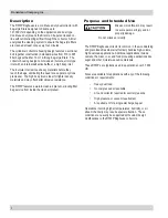
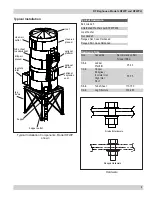
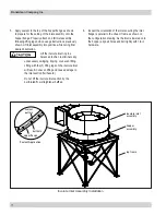
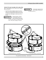
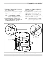
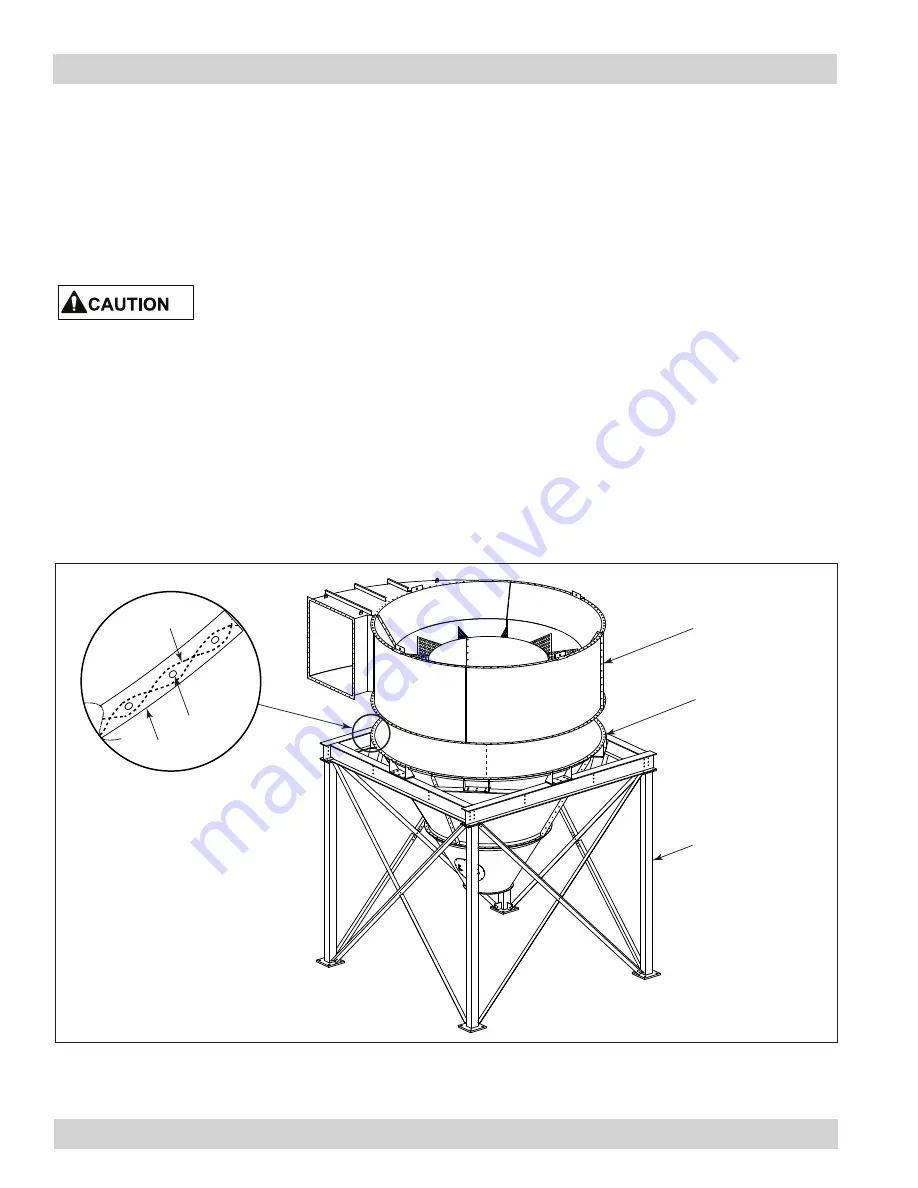
5. Apply sealant to the top of the hopper flange as shown
to prepare for the setting of the inlet assembly onto the
hopper flange. Properly attach and lift inlet assembly
following lifting lugs bolt-on usage instructions previously
shown. Lift inlet assembly into position while noting final
desired orientation.
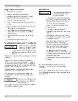
Lift the involute inlet ring in a
balanced fashion to eliminate any
unnecessary swinging, tipping, or uneven lifting.
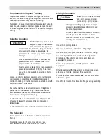
Lifting with the (3) lifting lugs on the involute inlet
will result in uneven lifting and cause damage to
the inlet section (fall hazard).
Do not lift the involute inlet section by the
perforated flow straightener baffles.
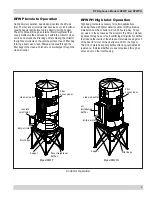
6. Inspect the orientation of the inlet ensuring the inlet
flange is parallel to the I-beam frame as shown on
the configuration drawing. As the inlet is lowered onto
the hopper, align all holes and bolt tightly with 1/2-in
hardware.
involute inlet
assembly
hopper
assembly
leg frame
sealant
pattern
upper flange
bolt hole
Sealant Application
Involute Inlet Assembly Installation

