5-28
EN
5.6.3.2 Installation
1.
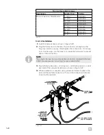
Install the network tees as shown in figure 5-23.
2.
Plug the harnesses in to the tees. The connectors are keyed so that
they only install in one way. Hand tighten the connections. Do not use
tools. Use tie wraps or other means to secure the harnesses to prevent
strain on the connection.
Figure 5-23.
Micro-c DeviceNet harness
Description
Length, ft (m)
Part No.
Micro-C Extension, Male/Female
1 (0.3)
CM10001
3 (0.9)
CM10003
6 (1.8)
CM10006
9 (2.7)
CM10009
12 (3.6)
CM10012
16 (4.9)
CM10016
20 (6.1)
CM10020
30 (9.1)
CM10030
Table 5-7.
3.
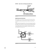
Ensure that you have two – and only two – terminating resistors, one at
each end of the network backbone, as shown in figure 5-22.
4.
When installation is complete, use a permanent marker to draw a line
across all DeviceNet connections. If one of the connections become
loose it will be evident.
NOTE
The actuator harness has two DeviceNet connectors, labeled CAN2 and
CAN3. Be sure you are connecting the one marked CAN2.
SCREWS IN ALL
MOUNT HOLES
EACH CABLE
APPROPRIATELY
SECURED AND
STRAIN RELIEVED
CLOSE TO TEES
NO PULLING
ON TEES
ALL NUTS DOUBLE
CHECKED FOR TIGHTNESS
AND MARKED
NOTE: TEES MAY NOT LOOK
EXACTLY AS SHOWN
Содержание OPTIMUS 360
Страница 36: ...4 6 EN This page left intentionally blank ...
Страница 68: ...5 32 EN This page left intentionally blank ...
Страница 80: ...A 2 EN This page left intentionally blank ...
Страница 82: ...A 4 EN This page left intentionally blank ...
Страница 84: ...A 6 EN This page left intentionally blank ...
Страница 86: ...A 8 EN This page left intentionally blank ...
Страница 88: ...A 10 EN This page left intentionally blank ...
Страница 90: ...A 12 EN This page left intentionally blank ...


