


5-10
EN
5.4.1
5.4.2
Planning
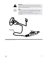
Before mounting the helm, you must be certain that you can route and
connect the CAN1 harnesses in such a way that they remain within the
maximum length and meet all requirements for system integrity. Review
section 5.5.2 before you proceed. It lists the relevant harness and
connection requirements.
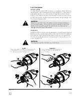
Helm installation
Find the installation diagram for your helm in the following pages.
Before beginning the installation, carefully unpack the helm from the box
and check that you have all the required hardware shown in the diagram.
NOTE
A mounting template for each helm type can be found in Appendix A. Make
sure you are using the correct template before drilling or cutting the dash.
The helm must be grounded to the negative bus or battery negative with
the supplied ground strap, as described below each installation diagram.
The steering sensor may be damaged by static electricity discharge if the
ground strap is not installed.
We recommend that you note the type and serial number of each helm
in the table below. In a multi-station system, the serial number will be
required during the system setup. The helm type may be useful to the
owner in the future.
STATION HELM TYPE
SERIAL No.
Main
Front Mount
Sport Plus Tilt
Classic Tilt
Rear Mount
Second
Front Mount
Sport Plus Tilt
Classic Tilt
Rear Mount
Table 5-3.
Содержание OPTIMUS 360
Страница 36: ...4 6 EN This page left intentionally blank ...
Страница 68: ...5 32 EN This page left intentionally blank ...
Страница 80: ...A 2 EN This page left intentionally blank ...
Страница 82: ...A 4 EN This page left intentionally blank ...
Страница 84: ...A 6 EN This page left intentionally blank ...
Страница 86: ...A 8 EN This page left intentionally blank ...
Страница 88: ...A 10 EN This page left intentionally blank ...
Страница 90: ...A 12 EN This page left intentionally blank ...


